Lecture-6: Overview
Various systems of Power Transmission
Comparison of conductor material in overhead system
Various Systems of Power Transmission
\(3\phi\), 3-wire a.c system is university adopted for transmission
Other systems used under special circumstances
D.C. system
D.C. 2-wire
D.C. 2-wire with mid-point earthed
D.C. 3-wire
\(1\phi\) A.C. system
\(1\phi\) 2-wire
\(1\phi\) 2-wire with mid-point earthed
\(1\phi\) 3-wire
\(2\phi\) A.C. Systems
\(2\phi\) 3-wire
\(2\phi\) 4-wire
\(3\phi\) A.C. Systems
\(3\phi\) 3-wire
\(3\phi\) 4-wire
Criteria to Determine the Best System
Best system \(\Rightarrow\) cost of conductor material \(\Rightarrow\) min. volume
Comparing basis : equal maximum stress on the dielectric
Two case are there
Overhead (OH) system
max. disruptive stress exists between conductor and earth
comparison basis: maxm. voltage between conductor and earth
Underground (UG)system
chief stress on insulation is between the conductors
basis of maximum potential difference between conductors
Assumptions in each case:
same power (\(P~wattts\)) transmitted by each system
distance (\(l~meters\)) of transmission remains the same
line losses (\(W~watts\)) are same
max. voltage between conductor and earth is same
Overhead System
2-wire d.c. system with one conductor earthed
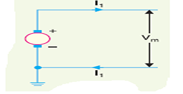
Max. voltage between conductors \(=V_{m}\)
Power to be transmitted \(=P\)
Load current, \(I_{1}=P / V_{m}\)
\(R_{1}=\rho l / a_{1}\) is the resistance of each line conductor
\(\quad W=2 I_{1}^{2} R_{1}=2\left(\frac{P}{V_{m}}\right)^{2} \rho \frac{l}{a_{1}}\)
Area of \(\mathrm{X}\) -section, \(a_{1}=\frac{2 P^{2} \rho l}{W V_{m}^{2}}\)
- Volume of conductor material required\[=2 a_{1} l=2\left(\frac{2 P^{2} \rho l}{W V_{m}^{2}}\right) l=\frac{4 P^{2} \rho l^{2}}{W V_{m}^{2}} =K~( say)\]
usual practice to make this system as the basis for comparison
Two-wire d.c. system with mid-point earthed
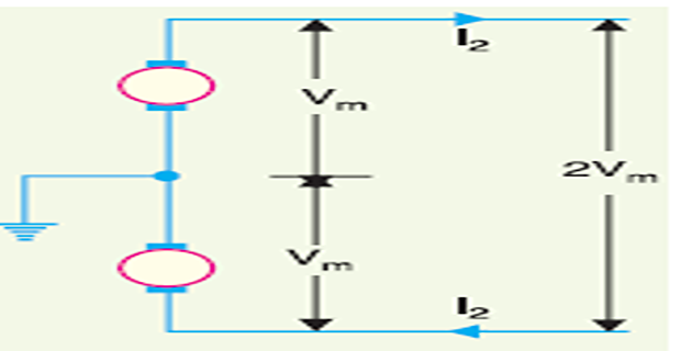
Load current, \(I_{2}=P / 2 V_{m}\)
- Line losses\[\begin{aligned} W &=2 I_{2}^{2} R_{2}=2\left(\frac{P}{2 V_{m}}\right)^{2} \times \frac{\rho l}{a_{2}} \\ &\left[\because R_{2}=\rho l / a_{2}\right] \\ \therefore \quad W &=\frac{P^{2} \rho l}{2 a_{2} V_{m}^{2}} \end{aligned}\]
Area of \(\mathrm{X}\) -section, \(a_{2}=\frac{P^{2} \rho l}{2 W V_{m}^{2}}\)
- Volume of conductor material required\[=2 a_{2} l=2\left(\frac{P^{2} \rho l}{2 W V_{m}^{2}}\right) l=\frac{P^{2} \rho l^{2}}{W V_{m}^{2}} =\dfrac{K}{4}\]
Three-wire d.c. system
Assume balanced loads & neutral wire X-section area = \(1/2^\ast\) outer wire
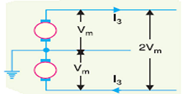
Load current, \(I_{3}=P / 2 V_{m}\)
- Line losses\[\begin{array}{l} W=2 I_{3}^{2} R_{3}=2\left(\frac{P}{2 V_{m}}\right)^{2} \times \rho \frac{l}{a_{3}}\\ =\frac{P^{2} \rho l}{2 V_{m}^{2} a_{3}} \end{array}\]
Area of \(\mathrm{X}\) -section, \(a_{3}=\frac{P^{2} \rho l}{2 W V_{m}^{2}}\)
- Volume of conductor material required\[\begin{array}{l} =2 \cdot 5 a_{3} l=2 \cdot 5\left(\frac{P^{2} \rho l}{2 W V_{m}^{2}}\right) l \\ =\frac{2 \cdot 5}{2}\left(\frac{P^{2} \rho l^{2}}{W V_{m}^{2}}\right) =\frac{5}{16} K \end{array}\]
\(1\phi\), 2-wire a.c. system with one conductor earthed
R.M.S value of the voltage = \(V_m / \sqrt{2}\). Assume the p.f. of the load \(=\cos\phi\)
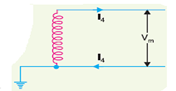
\(\text { Load current, } I_{4}=\frac{P}{\left(V_{m} / \sqrt{2}\right) \cos \phi}=\frac{\sqrt{2} P}{V_{m} \cos \phi}\)
\(\text { Line losses, } W=2 I_{4}^{2} R_{4}=2\left(\frac{\sqrt{2} P}{V_{m} \cos \phi}\right)^{2} \times \frac{\rho l}{a_{4}}=\frac{4 P^{2} \rho l}{\cos ^{2} \phi V_{m}^{2} a_{4}}\)
\(\text { Area of } \mathrm{X} \text { -section, } a_{4}=\frac{4 \mathrm{P}^{2} \mathrm{p} \mathrm{l}}{\cos ^{2} \phi \mathrm{W} V_{m}^{2}}\)
- Volume of conductor material required\[\begin{array}{l} =2 a_{4} l=2\left(\frac{4 P^{2} \rho l}{V_{m}^{2} W \cos ^{2} \phi}\right) l \\ =\frac{2}{\cos ^{2} \phi} \times \frac{4 P^{2} \rho l^{2}}{W V_{m}^{2}} =\frac{2 K}{\cos ^{2} \phi} \end{array}\]
\(1\phi\), 2-wire system with mid-point earthed
R.M.S value of the voltage = \(2 V_{m} / \sqrt{2}=\sqrt{2} V_{m}\)
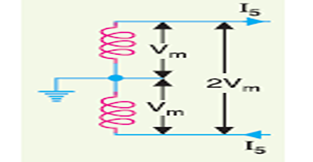
\(\text { Load current, } I_{5}=\frac{P}{\sqrt{2} V_{m} \cos \phi}\)
- \(\text { Line losses, } W=2 I_{5}^{2} R_{5}=2\left(\frac{P}{\sqrt{2} V_{m} \cos \phi}\right)^{2} R_{5}\)\[W=\frac{P^{2} \rho l}{a_{5} V_{m}^{2} \cos ^{2} \phi}\]
\(\text { Area of } \mathrm{X} \text { -section, } a_{5}=\frac{P^{2} \rho l}{W V_{m}^{2} \cos ^{2} \phi}\)
- Volume of conductor material required\[\begin{array}{l} =2 a_{5} l=2\left(\frac{P^{2} \rho l}{W V_{m}^{2} \cos ^{2} \phi}\right) l=\frac{2 P^{2} \rho l^{2}}{W V_{m}^{2} \cos ^{2} \phi} \\ =\frac{2}{\cos ^{2} \phi} \times \frac{P^{2} \rho l^{2}}{W V_{m}^{2}} =\frac{K}{2 \cos ^{2} \phi} \end{array}\]
\(1\phi\), 3-wire system
RM.S.value of voltage between conductors \(=2 V_{m} / \sqrt{2}=\sqrt{2} V_{m}\)
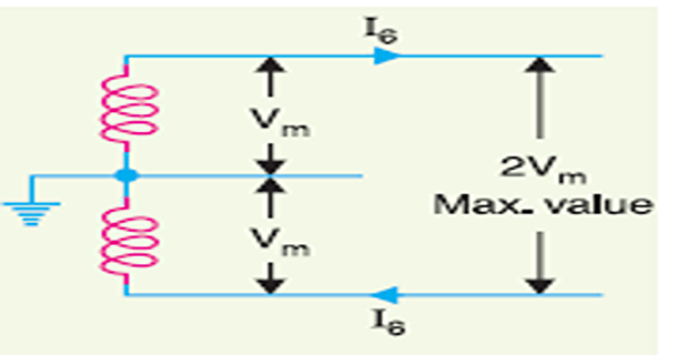
\(\text { Load current, } I_{6}=\frac{P}{\sqrt{2} V_{m} \cos \phi}\)
- \(\text { Line losses, } W =2 I_{6}^{2} R_{6}\)\[\begin{aligned} & =2\left(\frac{P}{\sqrt{2} V_{m} \cos \phi}\right)^{2} \times \frac{\rho l}{a_{6}} =\frac{P^{2} \rho l}{a_{6} V_{m}^{2} \cos ^{2} \phi} \end{aligned}\]
\(\text { Area of } \mathrm{X} \text { -section, } a_{6}=\frac{P^{2} \rho l}{W V_{m}^{2} \cos ^{2} \phi}\)
- Volume of conductor material required\[\begin{array}{l} =2 \cdot 5 a_{6} l=2 \cdot 5\left(\frac{P^{2} \rho l}{W V_{m}^{2} \cos ^{2} \phi}\right) l=\frac{2 \cdot 5 P^{2} \rho l^{2}}{W V_{m}^{2} \cos ^{2} \phi} \\ =\frac{2 \cdot 5}{\cos ^{2} \phi} \times \frac{P^{2} \rho l^{2}}{W V_{m}^{2}} =\frac{5 K}{8 \cos ^{2} \phi} \end{array}\]
\(2\phi\), 4-wire a.c. system
R.M.S. value of voltage \(=2 V_{m} / \sqrt{2}=\sqrt{2} V_{m}\)
Power supplied per phase (i.e., by outers \(A\) and \(B\) ) \(=P / 2\)
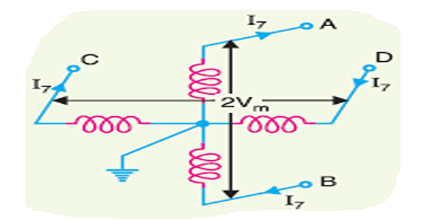
\(\text { Load current, } I_{7}=\frac{P / 2}{\sqrt{2} V_{m} \cos \phi}=\frac{P}{2 \sqrt{2} V_{m} \cos \phi}\)
\(\text { Line losses, } W=4 I_{7}^{2} R_{7}=4\left(\frac{P}{2 \sqrt{2} V_{m} \cos \phi}\right)^{2} \times \frac{\rho l}{a_{7}}=\frac{P^{2} \rho l}{2 a_{7} V_{m}^{2} \cos ^{2} \phi}\)
\(\text { Area of } \mathrm{X} \text { -section, } a_{7}=\frac{P^{2} \rho l}{2 W V_{m}^{2} \cos ^{2} \phi}\)
- Volume of conductor material required\[\begin{array}{l} =4 a_{7} l =4\left(\frac{P^{2} \rho l}{2 W V_{m}^{2} \cos ^{2} \phi}\right) l=\frac{4 P^{2} \rho l^{2}}{2 W V_{m}^{2} \cos ^{2} \phi} \\ =\frac{1}{2 \cos ^{2} \phi} \times \frac{4 P^{2} \rho l^{2}}{W V_{m}^{2}} =\frac{K}{2 \cos ^{2} \phi} \end{array}\]
\(2\phi\), 3-wire system
R.M.S voltage between outgoing conductor and neutral \(=V_{m} / \sqrt{2}\)
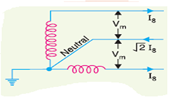
\(\text { Current in each outer, } I_{8}=\frac{P / 2}{\frac{V_{m}}{\sqrt{2}} \cos \phi}=\frac{P}{\sqrt{2} V_{m} \cos \phi}\)
Current in neutral wire \(=\sqrt{I_{8}^{2}+I_{8}^{2}}=\sqrt{2} I_{8}\)
Assuming the current density to be constant, the area of X-section of the neutral wire will be \(\sqrt{2}\) \(*\) either of the outers.
\(\text { Resistance of neutral wire }=\frac{R_{8}}{\sqrt{2}}=\frac{\rho l}{\sqrt{2} a_{8}}\)
\(\text { Line losses, } W =2 I_{8}^{2} R_{8}+\left(\sqrt{2} I_{8}\right)^{2} \frac{R_{8}}{\sqrt{2}}=I_{8}^{2} R_{8}(2+\sqrt{2})\)
\(3\phi\), 3-wire system
may be star-connected or delta-connected
R.M.S. voltage per phase \(=V_{m} / \sqrt{2}\) (assuming Y)
Power transmitted per phase \(=P / 3\)
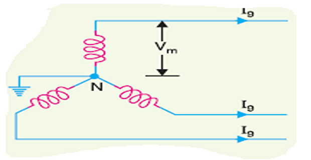
Load current per phase, \(I_{9}=\frac{P / 3}{\left(V_{m} / \sqrt{2} \cos \phi\right)}=\frac{\sqrt{2} P}{3 V_{m} \cos \phi}\)
Line losses, \(W=3 I_{9}^{2} R_{9}=3\left(\frac{\sqrt{2} P}{3 V_{m} \cos \phi}\right)^{2} \frac{\rho l}{a_{9}}=\frac{2 P^{2} \rho l}{3 a_{9} V_{m}^{2} \cos ^{2} \phi}\)
Area of \(\mathrm{X}\) -section, \(a_{9}=\frac{2 P^{2} \rho l}{3 W V_{m}^{2} \cos ^{2} \phi}\)
- Volume of conductor material required\[\begin{array}{l} =3 a_{9} l=3\left(\frac{2 P^{2} \rho l}{3 W V_{m}^{2} \cos ^{2} \phi}\right) l=\frac{2 P^{2} \rho l^{2}}{W V_{m}^{2} \cos ^{2} \phi} \\ =\frac{0 \cdot 5 K}{\cos ^{2} \phi} \end{array}\]
\(3\phi\), 4-wire system
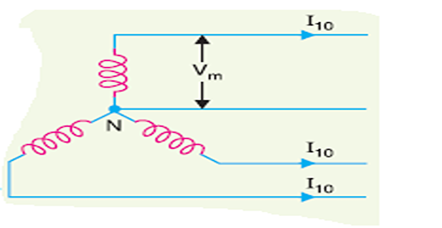
- , 3 -wire Same as Line losses,\[=\frac{2 P^{2} \rho l}{3 a_{10} V_{m}^{2} \cos ^{2} \phi}\]
Area of \(\mathrm{X}\) -section, \(a_{10}=\frac{2 P^{2} \rho l}{3 W V_{m}^{2} \cos ^{2} \phi}\)