Demonstrative Video
Lecture-7: Overview
Variable load Demand in Power Station
Problems with Variable Load Demand
Various Load Curves
Importance of Load Curve
Load Characteristics Terms & Definitions
Types of Loads
Methods of Meeting the increasing load demand
Power Station Variable Load Demand
PS delivers power to a large number of consumers
Power demands varies in accordance with consumers activities
PS load is never constant varies from time to time.
Complexities of modern power plant operation arise from the inherent variability of the load demanded by the users.
PS must produce electric power as and when demanded to meet the requirements as it cannot be stored
On one hand, the power engineer would like that the alternators in the PS should run at their rated capacity for \(\eta_{max}\) & on the other hand, the demands of the consumers have wide variations.
This makes the design of a power station highly complex.
Focus our attention on the problems of variable load on PS.
Problems of Variable Load on PS
PS load varies from time to time due to uncertain demands of the consumers known as variable load on the station
Need of additional equipment:
\(\uparrow\) power demand must be followed by \(\uparrow\) flow of coal, air and water to the boiler
additional equipment has to be installed to accomplish this job.
Increase in production cost:
Alternator operates at \(\eta_{max}\) near its rated capacity
single alternator if used will have poor \(\eta\) during periods of light loads on the plant
In actual practice, a number of alternators of different capacities are installed operated at nearly F.L capacity
Use of a number of generating units increases the initial cost per kW of the plant capacity as well as floor area required
This leads to the increase in production cost of energy
Load Curves
Curve showing the variation of load on the PS w.r.t time is known as a load curve
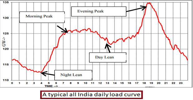
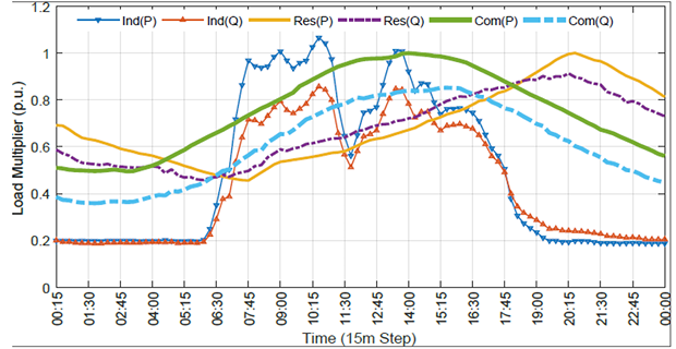
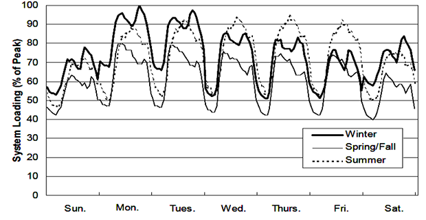
daily LC: whole day (i.e., 24 hours) are recorded half-hourly or hourly and are plotted against time
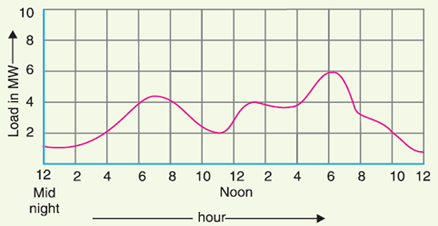
monthly LC: daily load curves of a month
average values of power over a month at different times of the day are calculated
generally used to fix the rates of energy
yearly LC: monthly load curves of that particular year
generally used to determine the annual load factor
Importance of Daily Load Curve ( DLC)
shows variations of load on PS during different hours of the day
- \[\text{ Units generated/day} = \text{Area (in kWh) under the daily LC }\]in the day area under the curve gives
highest point on DLC \(\Rightarrow\) maximum demand on the station on that day
Area under DLC divided by the total number of hours gives the Average Load on the station in the day
\[\text{Average load} =\frac{\text { Area (in } \mathrm{kWh} \text { ) under daily load curve }}{24 \text { hours }}\]ratio of the area under DLC to the total area of rectangle in which it is contained gives the load factor
\[\begin{aligned} \text { Load factor } &=\frac{\text { Average load }}{\text { Max. demand }}\\ &=\frac{\text { Average } \operatorname{load} \times 24}{\text { Max. demand } \times 24} \\ & =\frac{\text { Area (in kWh) under DLC }}{\text { Total area of rectangle LC is contained }} \end{aligned}\]helps in selecting the size and number of generating units
helps in preparing the operation schedule of the station
Important Terms & Factors
Connected load: sum of continuous ratings of all the equipments connected to supply system.
Maximum demand: greatest demand of load on the power station during a given period.
- \[\text{Demand factor} =\frac{\text { Maximum demand }}{\text { Connected load }} < 1\]Demand factor
Average load
Load factor
\(\Rightarrow\) ratio of average load to MD during a given period
\(\uparrow\) LF \(\Rightarrow\) MD \(\downarrow\) \(\Rightarrow\) cost per unit generated \(\downarrow\)
Station capacity selected to meet the MD
\(\downarrow\) MD \(\Rightarrow\) \(\downarrow\) plant capacity \(\Rightarrow\) \(\downarrow\) cost of the plant.
Diversity factor
PS supplies load to various types of consumers whose MDs generally do not occur at the same time.
MD on the PS is always \(<\) sum of individual MDs of the consumers \(\Rightarrow\) DF \(>\) 1.
\(\uparrow\) DF \(\Rightarrow\) cost of generation of power \(\downarrow\).
\(\uparrow\) DF \(\Rightarrow\) MD \(\downarrow\) \(\Rightarrow\) plant capacity \(\downarrow\) \(\Rightarrow\) capital investment \(\downarrow\)
Plant capacity factor
Plant CF is an indication of the reserve capacity of the plant
PS is so designed that it has some reserve capacity for meeting the increased load demand in future
- \[\text{Reserve capacity} = \text{Plant capacity} - \text{Max. demand}\]Therefore, the installed capacity of the plant is always somewhat greater than the MD on the plant
Difference between load factor and plant capacity factor is an indication of reserve capacity
If MD on the plant \(=\) to the plant capacity, then load factor and plant CF will have the same value
In such a case, the plant will have no reserve capacity.
Plant use factor
Units Generated per Annum
It is often required to find the \(\mathrm{kWh}\) generated per annum from maximum demand and load factor.
The procedure is as follows:
Load Duration Curve
\(\Rightarrow\) Load elements of a LC are arranged in the order of descending magnitudes
- LDC is obtained from the same data as the LC but the ordinates
are arranged in the order of descending magnitudes
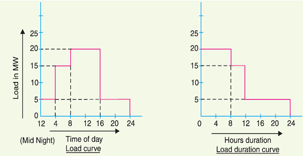
maximum load is represented to the left and decreasing loads are represented to the right in the descending order
Important Points:
LDC gives the data in a more presentable form
readily shows the number of hours during which the given load has prevailed
The area under LDC is equal to that of the corresponding LC
area under daily LDC (in kWh) will give the units generated on that day.
LDC can be extended to include any period of time
By laying out the abscissa from 0 hour to 8760 hours, the variation and distribution of demand for an entire year can be summarised in one curve.
The curve thus obtained is called the annual load duration curve
Types of Loads
Domestic load
lights, fans, refrigerators, heaters, television, small motors for pumping water etc.
Most of the residential load occurs only for some hours during the day (i.e., 24 hours) e.g., lighting load occurs during night time and domestic appliance load occurs for only a few hours.
For this reason, the load factor is low (10% to 12%)
Commercial load
lighting for shops, fans and electric appliances used in restaurants etc.
occurs for more hours during the day as compared to the domestic load.
has seasonal variations due to the extensive use of air-conditioners and space heaters.
Industrial load
consists of load demand by industries
magnitude depends upon the type of industry.
Thus small scale industry requires load upto 25 kW, medium scale industry between 25kW and 100 kW and large-scale industry requires load above 500 kW.
generally not weather dependent
Municipal load
street lighting, power required for water supply and drainage purposes.
Street lighting load is practically constant throughout the hours of the night.
For water supply, water is pumped to overhead tanks by pumps driven by electric motors. Pumping is carried out during the off-peak period, usually occurring during the night.
This helps to improve the load factor of the power system.
Irrigation load
electric power needed for pumps driven by motors to supply water to fields.
supplied for 12 hours during night
Traction load
includes tram cars, trolley buses, railways etc
has wide variation.
During the morning hour, it reaches peak value because people have to go to their work place.
After morning hours, the load starts decreasing and again rises during evening since the people start coming to their homes.
Base Load and Peak Load on Power Station
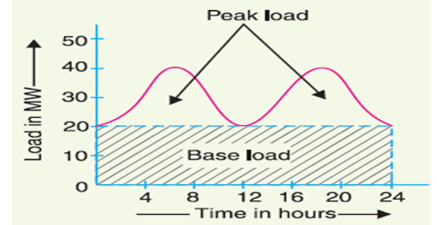
Base load: The unvarying load which occurs almost the whole day on the station
Peak load: The various peak demands of load over and above the base load of the station
Method of Meeting the Load
the best method interconnect two different power stations
The more efficient plant is used to supply the base load and is known as base load power station.
The less efficient plant is used to supply the peak loads and is known as peak load power station.
Interconnected Grid System
\(\Rightarrow\) connection of several generating stations in parallel
Exchange of peak loads
Use of older plants
Ensures economical operation
Increases diversity factor
Reduces plant reserve capacity
Increases reliability of supply