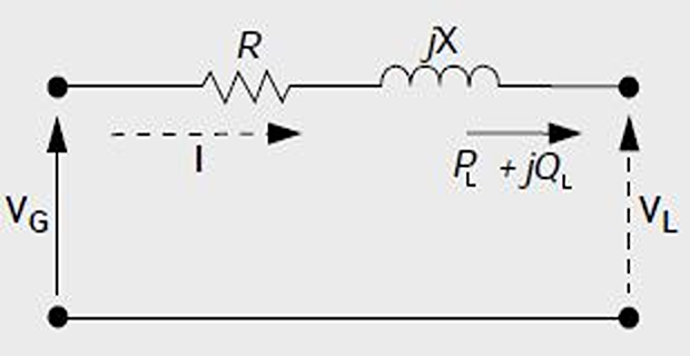
Power flow in a two bus-bar system

are shown by solid line (with an arrow showing the direction) and by dotted line
Power injected by generator and voltage both are specified
- equation that links the complex power with the voltage and current at the generator busbar\[S_{G}=P_{G}+jQ_{G}=V_{G}I^{*}\]
- the current through the line can be calculated as\[I=\dfrac{P_{G}-jQ_{G}}{V_{G}^{*}}\]
- Then, voltage at the load busbar\[\begin{aligned} V_{L} & =V_{G}-\left(R+jX\right)I\\ & =V_{G}-\left(R+jX\right)\left[\dfrac{P_{G}-jQ_{G}}{V_{G}^{*}}\right] \end{aligned}\]
By defining, \(V_{G}=V_{G}\angle\delta \Longrightarrow V_{G}^{*}=V_{G}\angle-\delta\)
- Therefore:\[V_{L}=V_{G}\angle\delta-\left[\dfrac{RP_{G}+XQ_{G}}{V_{G}\angle-\delta}\right]-j\left[\dfrac{XP_{G}-RQ_{G}}{V_{G}\angle-\delta}\right]\]
Generator busbar volatge and power at the load busbar is known
A simple two bus-bar system, load power and generator voltage are given The complex load power is
\[S_{L}=P_{L}+jQ_{L}=V_{L}I^{*}\]Although the load power is known but load voltage is unknown, hence current cannot be determined
- The generator power is\[S_{G}=P_{G}+jQ_{G}=V_{G}I^{*}\]
Again the current cannot be calculated, as the power at the generator is unknown
- The load voltage does not have a closed form solution\[V_{L}=V_{G}-\left(R+jX\right)\left[\dfrac{P_{L}-jQ_{L}}{V_{L}^{*}}\right]\]
- is non-linear as it contains the product of the voltages at the load equation in relation to\[V_{L}V_{L}^{*}=V_{G}V_{L}^{*}-\left(R+jX\right)\left(P_{L}-jQ_{L}\right)\]
Solving the equation requires an iterative method
The solution can start with an initial value of \(V_L^{(0)}\), then find \(V_L^{*(0)}\)
A new value of \(V_L^{(1)}\) is calculated from the equation
The process is repeated for several iterations until the voltage of one iteration converges to the next iteration
Once \(V_L\) is obtained \(I\) can be calculated
Active losses = \(I^{2}R,\)
The active power output of the generator \(\Longrightarrow P_G = P_L + I^2R\)Reactive losses = \(I^2X\)
The reactive power production of the generator \(\Longrightarrow Q_G = Q_L +I^2X\)
Real And Reactive Power Injected in a Bus
- bus be denoted by Let the voltage at the\[V_{i}=\left|V_{i}\right|\angle\delta_{i}=\left|V_{i}\right|\left(cos\delta_{i}+jsin\delta_{i}\right)\]
- as Also let us define the self admittance at bus-\[Y_{ii}=\left|Y_{ii}\right|\angle\theta_{ii}=\left|Y_{ii}\right|\left(cos\theta_{ii}+jsin\theta_{ii}\right)=G_{ii}+jB_{ii}\]
- can be written as and Similarly the mutual admittance between the buses\[Y_{ij}=\left|Y_{ij}\right|\angle\theta_{ij}=\left|Y_{ij}\right|\left(cos\theta_{ij}+jsin\theta_{ij}\right)=G_{ij}+jB_{ij}\]
- is given as buses. The current injected at bus-Let the power system contains a total number of\[I_{i}=Y_{i1}V_{1}+Y_{i2}V_{2}+\cdots+Y_{in}V_{n}={\displaystyle \sum_{k=1}^{n}Y_{ik}V_{k}}\]
Note: assume current entering a bus to be \(+ve\) and that leaving the bus to be \(-ve\).
As a consequence the active power and reactive power entering a bus will also be assumed to be \(+ve\).
The complex power at bus-\(i\) is then given by
\[ \begin{aligned} P_{i}-jQ_{i} & =V_{i}^{*}I_{i}=V_{i}^{*}{\displaystyle \sum_{k=1}^{n}Y_{ik}V_{k}}\\ & =\left|V_{i}\right|\left(cos\delta_{i}-jsin\delta_{i}\right){\displaystyle \sum_{k=1}^{n}\left|Y_{ik}V_{k}\right|\left(cos\theta_{ik}+jsin\theta_{ik}\right)\left(cos\delta_{k}+jsin\delta_{k}\right)}\\ & ={\displaystyle \sum_{k=1}^{n}\left|Y_{ik}V_{i}V_{k}\right|\left(cos\delta_{i}-jsin\delta_{i}\right)\left(cos\theta_{ik}+jsin\theta_{ik}\right)\left(cos\delta_{k}+jsin\delta_{k}\right)} \end{aligned} \]
- Note:\[\begin{aligned} & \left(cos\delta_{i}-jsin\delta_{i}\right)\left(cos\theta_{ik}+jsin\theta_{ik}\right)\left(cos\delta_{k}+jsin\delta_{k}\right)\\ = & \left(cos\delta_{i}-jsin\delta_{i}\right)\left[cos\left(\theta_{ik}+\delta_{k}\right)+jsin\left(\theta_{ik}+\delta_{k}\right)\right]\\ = & cos\left(\theta_{ik}+\delta_{k}-\delta_{i}\right)+jsin\left(\theta_{ik}+\delta_{k}-\delta_{i}\right) \end{aligned}\]
Finally, the real and reactive power can be expressed as
equation*\[\begin{aligned} P_{i} & ={\displaystyle \sum_{k=1}^{n}\left|Y_{ik}V_{i}V_{k}\right|cos\left(\theta_{ik}+\delta_{k}-\delta_{i}\right)}\\ Q_{i} & =-{\displaystyle \sum_{k=1}^{n}\left|Y_{ik}V_{i}V_{k}\right|sin\left(\theta_{ik}+\delta_{k}-\delta_{i}\right)} \end{aligned}\]
Preparation of Data For Load Flow
- Let\[\begin{array}{cc} P_{Gi}: & \mbox{real power generated at bus-}i\\ Q_{Gi}: & \mbox{reactive power generated at bus-}i\\ P_{Li}: & \mbox{real power consumed at the }i^{th}~\mbox{bus}\\ Q_{Li}: & \mbox{reactive power consumed at the }i^{th}~\mbox{bus} \end{array}\]
- is Then the net real power injected in bus-\[P_{i,inj}=P_{Gi}-P_{Li}\]
Let the injected power calculated by the load flow program be \(P_{i,calc}\) and \(Q_{i,calc}\). Then the mismatch between the actual injected and calculated values is given by
equation*\[\begin{aligned} \varDelta P_{i} & =P_{i,inj}-P_{i,calc}=P_{Gi}-P_{Li}-P_{i,calc}\\ \varDelta Q_{i} & =Q_{i,inj}-Q_{i,cal}=Q_{Gi}-Q_{Li}-Q_{i,calc} \end{aligned}\]
The purpose of the load flow is to minimize the above two mismatches.
Real and reactive power can be calculated from the derived equations.
Since the magnitudes of all the voltages and their angles are not known a priori, an iterative procedure must be used to estimate the bus voltages and their angles in order to calculate the mismatches.
It is expected that mismatches \(\varDelta P_{i}\) and \(\varDelta Q_{i}\) reduce with each iteration and the load flow is said to have converged when the mismatches of all the buses become less than a very small number.
Consider a system with
2 generator and 3 load buses
bus-1 as the slack bus while taking bus-5 as the P-V bus
Buses 2, 3 and 4 are P-Q buses


\(|V|, \delta, P_G, Q_G, P_L, Q_L\) at each bus are given
some \(|V|\) and \(\delta\) are given in boldface letters indicating that these are initial data used for starting the load flow program
we do not need to calculate the quantities shown by dash (–), hence their initial estimates are not given
Also note that the slack bus does not contain any load while the P-V bus 5 has a local load and this is indicated in the load column
Load Flow Problem
The basic power flow equations are nonlinear
In an \(n\)-bus power system: , \(n_p\): number of \(P-Q\) bus and \(n_q\): number of \(P-V\) bus
Unnown quantities:: \(2n_p\) (\(V\) and \(\delta\) of the P-Q buses) + \(n_g\) (\(\delta\) of the P-V buses), total quantities to be determined
Known quantities:: \(2n_p\) (real and reactive power of \(P-Q\) bus) + \(2n_g\) (real power and voltage magnitude of \(P-V\) bus) + voltage magnitude and angle of slack bus
Although sufficient numbers of known quantities are available, but closed form equations cannot be formed, hence have to resort iterative methods to obtain the load flow solutions
At the beginning a set of values for the unknown quantities are chosen
These are then updated at each iteration
The process continues till errors between all the known and actual quantities reduce below a pre-specified value