Load Flow by Gauss-Seidel Method
Denote the initial voltage of the \(i^{th}\) bus at the \(0^{th}\) iteration or initial guess by \(V_{i}^{(0)}\), \(i=2,\cdots,n\)
The voltage at the first iteration is \(V_{i}^{(1)}\) and so on
\(P-V\) and \(P-Q\) buses are treated differently
However in both these type of buses we use the complex power equation for updating the voltages
\[ $ \begin{aligned} P_{i,inj}-jQ_{i,inj} & =V_{i}^{*}{\displaystyle \sum_{k=1}^{n}Y_{ik}V_{k}=V_{i}^{*}\left[Y_{i1}V_{1}+Y_{i2}V_{2}+\cdots+Y_{ii}V_{i}+\cdots+Y_{in}V_{n}\right]}\\ V_{i} & =\dfrac{1}{Y_{ii}}\left[\dfrac{P_{i,inj}-jQ_{i,inj}}{V_{i}^{*}}-Y_{i1}V_{1}-Y_{i2}V_{2}-\cdots-Y_{in}V_{n}\right] \end{aligned} \]In this fashion the voltages of all the buses are updated
- Even though the real power is specified, the reactive power is unknown that has to be determined to update the bus voltage.\[\begin{aligned} Q_{i,inj}&=-Im\left[V_{i}^{*}{\displaystyle \sum_{k=1}^{n}Y_{ik}V_{k}}\right]\\ &=-Im\left[V_{i}^{*}\left(Y_{i1}V_{1}+Y_{i2}V_{2}+\cdots+Y_{ii}V_{i}+\cdots+Y_{in}V_{n}\right)\right] \end{aligned}\]
- -iteration can be written as The\[ $ Q_{i,inj}^{(k)}=-Im\left[V_{i}^{*(k-1)}\left(Y_{i1}V_{1}+Y_{i2}V_{2}^{(k)}+\cdots+Y_{ii}V_{i}^{(k-1)}+\cdots+Y_{in}V_{n}^{(k-1)}\right)\right] \]
- -bus of the system The reactive power for the\[Q_{5,inj}^{(1)}=-Im\left[V_{5}^{*(0)}\left(Y_{51}V_{1}+Y_{52}V_{2}^{(1)}+Y_{53}V_{3}^{(1)}+Y_{54}V_{4}^{(1)}+Y_{55}V_{5}^{(0)}\right)\right]\]
- Once the reactive power is estimated, the bus-5 voltage is updated as\[ $ V_{5}^{(1)}=\dfrac{1}{Y_{55}}\left[\dfrac{P_{5,inj}-jQ_{5,inj}^{(1)}}{V_{5}^{*(0)}}-Y_{51}V_{1}-Y_{52}V_{2}^{(1)}-Y_{53}V_{3}^{(1)}-Y_{54}V_{4}^{(0)}\right] \]
Note: even though the power generation in bus-5 is 48 MW, there is a local load that is consuming half that amount.
Therefore the net power injected by this bus is 24 MW and consequently the injected power \(P_{5,inj}\) in this case is taken as 0.24 per unit.
The voltage is calculated as \(V_{5}^{(1)} = 1.0169\angle-0.8894^{0}\).
Unfortunately however the magnitude of the voltage obtained above is not equal to the magnitude given in Table.
- We must therefore force this voltage magnitude to be equal to that specified. This is accomplished by\[V_{5,corr}^{(1)}=|V_{5}|\times\dfrac{V_{5}^{(1)}}{|V_{5}^{(1)}|}\]
This will fix the voltage magnitude to be 1.02 per unit while retaining the phase of \(-0.8894^{\circ}\). The corrected voltage is used in the next iteration.
From table, total number of 4 real and 3 reactive powers are known to us.
We have to calculate these using the values of the voltage magnitudes and their angle obtained after each iteration.
The power mismatches are also to be calculated.
The process is assumed to have converged when each of \(\varDelta P_{2}\) , \(\varDelta P_{3}\), \(\varDelta P_{4}\), \(\varDelta P_{5}\), \(\varDelta Q_{2}\) , \(\varDelta Q_{3}\) and \(\varDelta Q_{4}\) is below a small pre-specified value.
At this point the process is terminated.
To accelerate the computation in the P-Q buses the obtained voltage is multiplied by an acceleration factor \((\lambda)\).
The value of \(\lambda\) has to be below 2.0 for the convergence to occur.
\[\begin{aligned} V_{i,acc}^{(k)} & =\left(1-\lambda\right)V_{i,acc}^{(k-1)}+\lambda V_{i}^{(k)}\\ & =V_{i,acc}^{(k-1)}+\lambda\left(V_{i}^{(k)}-V_{i,acc}^{(k-1)}\right) \end{aligned}\]
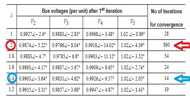
\(\bullet\) algorithm will start to diverge if larger value of \(\lambda\) is chosen