Contents
Inductance calculation
Inductance due to internal flux
Inductance due to external flux
Inductance of a single phase two wire line
Flux linkage of one conductor in a group
Inductance of composite conductor line
Inductance of \(3-\phi\) line with equilateral spacing
Inductance of \(3-\phi\) line with unsymmetrical spacing
Inductance of the conductor
- Inductance is defined as\[L=\dfrac{\lambda}{I}\]
Some lines of flux exist inside the conductor
Filaments on the surface of the conductor are not linked by internal flux
Flux linking the filament near the surface of the conductor is less than that of interior
ac flux induce higher voltage at the interior filament than that of surface
by Lenz’s law, induce voltage oppose change of current producing it
higher induced voltage at the inner filament cause higher current density at near the surface
causes higher effective resistance
skin effect is significant in large conductors

Inductance due to Internal Flux
Assuming return path of the current is very far, it does not effect the magnetic field, hence lines of flux are concentric with the conductor
- by Ampere’s law\[\mbox{mmf}=\oint H\centerdot ds=I~ At\]
\(H_x =\) field intensity at a distance \(x\) m from the center of the conductor, is constant and tangent to the circular path
is the current enclosed. where\[\begin{aligned} \oint H_{x}\centerdot ds & =I_{x}\\ H_{x}2\pi x & =I_{x} \end{aligned}\]
- Assuming uniform current density\[I_{x}=\dfrac{\pi x^{2}}{\pi r^{2}}I~ At/m\]
- m from the center of the conductor The flux density at\[B_{x}=\mu H_{x}=\dfrac{\mu xI}{2\pi r^{2}}~Wb/m^2\]
- The flux per m of length\[d\phi=\dfrac{\mu xI}{2\pi r^{2}}dx ~ Wb/m\]
- per m of length The flux linkage\[d\lambda=\dfrac{\pi x^{2}}{\pi r^{2}}d\phi=\dfrac{\mu x^{3}I}{2\pi r^{4}}dx ~ Wbt/m\]
- \(\mu_{0} = 4\pi \times 10^{-7}\)\(\mu_{r} = 1\)The total flux linkage inside the conductor\[\lambda_{int}=\intop_{0}^{r}\dfrac{\mu x^{3}I}{2\pi r^{4}}dx=\dfrac{\mu I}{8\pi} ~ Wbt/m\]\[ \boxed{L_{i n t}=\frac{1}{2} \times 10^{-7} \mathrm{H} / \mathrm{m}} \]
Inductance due to External Flux
- from the center of the conductor, the mmf around the element is At a distance\[2\pi xH_{x} = I\]
- The flux density in the element is given by\[B_{x}=\dfrac{\mu I}{2\pi x} ~ Wb/m^{2}\]
- in the tabular element The flux\[d\phi=\dfrac{\mu I}{2\pi x}dxWb/m\]
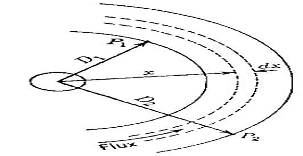
- and The flux linkage between\[\lambda_{12}=\intop_{D_{1}}^{D_{2}}\dfrac{\mu I}{2\pi x}dx=\dfrac{\mu I}{2\pi}ln\dfrac{D_{2}}{D_{1}}~Wbt/m\]\[L_{12} = 2\times 10^{-7}\ln\dfrac{D_2}{D_1}~\mathrm{H/m}\]
Inductance of a single-phase two-wire line
Line with two-conductors, one conductor being the return of the other
Flux set up due to the current in conductor 1 at a distance equal to or greater than \(\left(D+r_{2}\right)\) does not link the circuit
For \(\left(D+r_{2}\right)\) the fraction of the total current linked by the flux is 1.0.

Therefore, when \(D\) is much greater than \(r_1\) or \(r_2\), it is logical to use \(D\) instead of \(\left(D - r_{1}\right)\) or \(\left(D - r_{2}\right)\)
- Inductance (internal + external) of the circuit due to current in conductor 1\[L_{1}=\left(\dfrac{1}{2}+2ln\dfrac{D}{r_{1}}\right)\times10^{-7}~H/m\]
- \(r_{1}^{'} = 0.7788r_{1}\)\[L_{1}=2\times10^{-7}\left(ln~e^{1/4}+ln\dfrac{D}{r_{1}}\right)~ H/m\]In compact form\[L_{1}=2\times10^{-7}\left(ln\dfrac{D}{r_{1}e^{-1/4}}\right)=2\times10^{-7}\left(ln\dfrac{D}{r_{1}^{'}}\right) ~ H/m\]
The fictitious conductor, \(r_{1}^{'}\) assumed to have no internal flux but with the same inductance as the actual conductor
Current in conductor 2 flows in opposite direction (\(180^{0}\) phase shift), flux linkage produced by conductor 2 alone is in the same direction as conductor 1
Resulting flux is sum of the mmfs of both conductors
For constant permeability, flux linkage (or inductance) can be added
\[L=L_1+L_2 = 4\times 10^{-7}\left(\ln \dfrac{D}{\sqrt{r_1^{\prime}\cdot r_2^{\prime}}} \right)\]If \(r_{1}^{'} = r_{2}^{'} = r^{'}\), then
\[L= 4\times 10^{-7}\left(\ln\dfrac{D}{r^{\prime}} \right)\]
Flux linkages of one conductor in a group
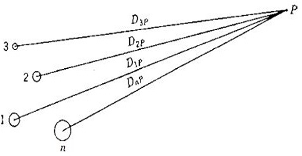
Conductors \(1,2,3..,n\) carry currents \(I_{1}, I_{2}, I_{3},...I_{n}\)
- Flux linkage of conductor 1 due to\[\lambda_{1P1}=2\times10^{-7}I_{1}ln\dfrac{D_{1P}}{r_{1}^{'}}~Wbt/m\]
- Flux linkage of conductor 1 due to\[\lambda_{1P2}=2\times10^{-7}I_{2}ln\dfrac{D_{2P}}{D_{12}}~Wbt/m\]
- Flux linkage of conductor 1 due to all conductors\[\lambda_{1P}=2\times10^{-7}\left(I_{1}ln\dfrac{D_{1P}}{r_{1}^{'}}+I_{2}ln\dfrac{D_{2P}}{D_{12}}+I_{3}ln\dfrac{D_{3P}}{D_{13}}+....I_{n}ln\dfrac{D_{nP}}{D_{1n}}\right)\]
- On expanding and regrouping the logarithmic terms\[\begin{aligned} \lambda_{1P} & =2\times10^{-7}\Bigg(I_{1}ln\dfrac{1}{r_{1}^{'}}+I_{2}ln\dfrac{1}{D_{12}}+I_{3}ln\dfrac{1}{D_{13}}+....I_{n}ln\dfrac{1}{D_{1n}}\\ & +I_{1}ln~D_{1P}+I_{2}ln~D_{2P}+I_{3}ln~D_{3P}+....+I_{n}ln~D_{nP}\Bigg) \end{aligned}\]
Since, \(I_{1}+I_{2}+ I_{3}+...+I_{n} = 0\)
Therefore, \(I_{n} = -(I_{1}+I_{2}+ I_{3}+...+I_{n-1})\)
- in the second term and regrouping Substituting\[\begin{aligned} \lambda_{1P} & =2\times10^{-7}\Bigg(I_{1}ln\dfrac{1}{r_{1}^{'}}+I_{2}ln\dfrac{1}{D_{12}}+I_{3}ln\dfrac{1}{D_{13}}+....I_{n}ln\dfrac{1}{D_{1n}}\\ & +I_{1}ln\dfrac{D_{1P}}{D_{nP}}+I_{2}ln\dfrac{D_{2P}}{D_{nP}}+I_{3}ln\dfrac{D_{3P}}{D_{nP}}+....+I_{\left(n-1\right)}ln\dfrac{D_{\left(n-1\right)P}}{D_{nP}}\Bigg) \end{aligned}\]
\(P\) is very far, the set of terms containing logarithms of ratios of distances from \(P\) becomes infinitesimal, since the ratio becomes 1
\[ \boxed{\lambda_{1 P}=2 \times 10^{-7}\left(I_1 \ln \frac{1}{r_1^{\prime}}+I_2 \ln \frac{1}{D_{12}}+I_3 \ln \frac{1}{D_{13}}+\ldots . I_n \ln \frac{1}{D_{1 n}}\right)~\mathrm{Wb}} \]
Inductance of composite conductor line

Stranded conductors comes under the classification of composite conductors
Assumption stands are identical and carry equal current
Conductor \(X\) \(\Longrightarrow\) \(n\) identical parallel filaments, each carrying \(I/n\)
Conductor \(Y\) \(\Longrightarrow\) return circuit for \(X\) carry \(-I/m\)
- \[\begin{aligned} \lambda_{a} & =2\times10^{-7}\dfrac{I}{n}\left(ln\dfrac{1}{r_{a}^{'}}+ln\dfrac{1}{D_{ab}}+ln\dfrac{1}{D_{ac}}+...+ln\dfrac{1}{D_{an}}\right)\\ & -2\times10^{-7}\dfrac{I}{m}\left(ln\dfrac{1}{D_{aa^{,}}}+ln\dfrac{1}{D_{ab^{'}}}+ln\dfrac{1}{D_{ac'}}+...+ln\dfrac{1}{D_{am}}\right) \end{aligned}\]Flux linkage of filament\[\begin{aligned} \lambda_{a} & =2\times10^{-7}I\cdot ln\dfrac{\sqrt[m]{D_{aa^{'}}D_{ab^{'}}D_{ac^{'}}...D_{am}}}{\sqrt[n]{r_{a^{'}}D_{ab}D_{ac}...D_{an}}} \end{aligned}\]
- Inductance of filament\[\begin{aligned} L_{a}=\dfrac{\lambda_{a}}{I/n} & =2n\times10^{-7}ln\dfrac{\sqrt[m]{D_{aa^{'}}D_{ab^{'}}D_{ac^{'}}...D_{am}}}{\sqrt[n]{r_{a^{'}}D_{ab}D_{ac}...D_{an}}}~ H/m \end{aligned}\]
- Similarly, inductance of filament\[\begin{aligned} L_{b}=\dfrac{\lambda_{b}}{I/n} & =2n\times10^{-7}ln\dfrac{\sqrt[m]{D_{ba^{'}}D_{bb^{'}}D_{bc^{'}}...D_{bm}}}{\sqrt[n]{D_{ba}r_{b^{'}}D_{bc}...D_{bn}}}~ H/m \end{aligned}\]
- The average inductance of the filaments of conductor\[L_{av} = \dfrac{L_{a}+L_{b}+L_{c}+...+L_{n}}{n}\]
- Since, all filaments have different inductance, the inductance of conductor\[L_{X} = \dfrac{L_{av}}{n} = \dfrac{L_{av}}{n^{2}}\]
Substituting the logarithmic expression
\[L_{x}=2\times10^{-7}\times ln\dfrac{\sqrt[mn]{\left(D_{aa'}D_{ab'}D_{ac'}\cdots D_{am}\right)\left(D_{ba'}D_{bb'}D_{bc'}\cdots D_{bm}\right)\ldots\left(D_{na'}D_{nb'}D_{nc'}\cdots D_{nm}\right)}}{\sqrt[n^{2}]{\left(D_{aa}D_{ab}D_{ac}\cdots D_{an}\right)\left(D_{ba}D_{bb}D_{bc}\cdots D_{bn}\right)\ldots\left(D_{na}D_{nb}D_{nc}\cdots D_{nn}\right)}}\]
Geometric Mean Distance, GMD \((D_m)\) : The \(mn^{th}\) root of the product of \(mn\) distance between conductor \(X\) and \(Y\)
Geometric Mean Radius, GMR \((D_s)\) : product of the distances from every filament in the conductor to itself and to every other filament.
\[L_x = 2 \times 10^{-7} \ln \dfrac{D_m}{D_s}\]Total inductance of the line
\[L = L_{x}+ L_{y}\]
Inductance of 3-phase line with equilateral spacing

Assuming balanced three-phase currents \(I_{a}+I_{b}+I_{c} = 0\)
Because of symmetry \(L_{a} = L_{b} = L_{c}\)
\[\lambda_{a} = 2 \times 10^{-7} \left(I_{a}~ln \dfrac{1}{D_{s}}+I_{b}~ln\dfrac{1}{D}+I_{c}~ln \dfrac{1}{D}\right)\]
Since \(I_{a} = -(I_{b}+I_{c})\), then
Inductance of 3-phase line with unsymmetrical spacing

Flux linkage and inductance of each phase are unequal, finding inductance is difficult
Results in unbalanced circuit
Transposition: Balance of \(3-\phi\) can be restored by exchanging the position of the conductors at regular intervals along the line so that each conductor occupies the original position every other conductor over an equal distance.
Transposition results in each conductor having the same average inductance over the whole cycle.
- occupying different position The avg. value of the flux linkage for\[\lambda_a = \dfrac{\lambda_{a1}+\lambda_{a2}+\lambda_{a3}}{3}\]\[\lambda_{a1}=2\times10^{-7}\left(I_{a}ln\dfrac{1}{D_{s}}+I_{b}ln\dfrac{1}{D_{23}}+I_{c}ln\dfrac{1}{D_{12}}\right)\]
- \(D_{eq} = \sqrt[3]{D_{12}D_{23}D_{31}}\)Avg. inductance per phase\[L_{a}=2\times10^{-7}\cdot ln \dfrac{D_{eq}}{D_s}\]