Ferranti effect
The effect of the TL in which \(V_r > V_s\) is known as the Ferranti effect.
Mainly occurs because of light load or open circuit at the receiving end
Ferranti effect is due to the charging current of the line.
When an ac voltage is applied, the current that flows into the capacitor is called charging current.
A charging current is also known as capacitive current.
The charging current increases in the line when \(V_r~>~V_s\)
The effect of the line capacitance is to cause the no-load receiving end voltage to be more than the sending end voltage
Effect is more pronounced as the line length increases
Cause of Ferranti Effect
\(C\) and \(L\) are the main parameters of the lines having a length 240 km or above.
On such TL, \(C\) is not concentrated at some definite points. It is distributed uniformly along the whole length of the line.
For \(V_s\) the current drawn by the capacitance of the line is more than current associated with the load.
Thus, at no load or light load, the \(V_r\) is quite large as compared to the constant voltage at the sending end.
- (no load) and Substituting\[V_{S}=\dfrac{V_{R}}{2}e^{\alpha l}e^{j\beta l}+\dfrac{V_{R}}{2}e^{-\alpha l}e^{-j\beta l}\]
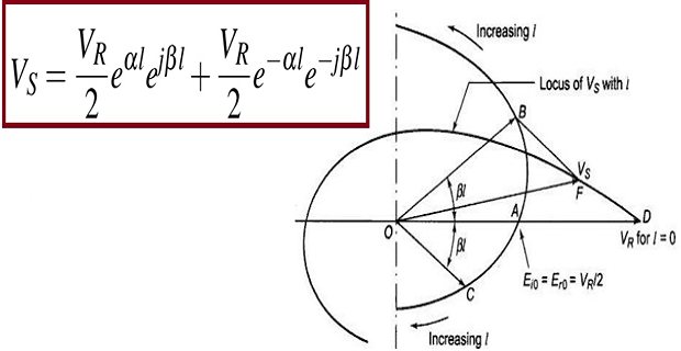
At \(l = 0\), both incident and reflected waves is \(V_{R}/2\)
As \(l\) increases
incident wave increases exponentially with \(\dfrac{V_{R}}{2} e^{\alpha t}\) and turns through positive angle \(\beta l\) (\(OB\))
reflected wave decreases exponentially with \(\dfrac{V_{R}}{2} e^{-\alpha t}\) and turns through negative angle \(\beta l\) (\(OC\))
The resultant phasor \(V_S\) (OF) is such that \(\left|V_{R}\right|>\left|V_{S}\right|\)