Demonstrative Video
Introduction
instrument for measuring the average (or real) power (\(\mathrm{P}\)) in single-phase circuits.
- balanced system. in a A can measure\[\begin{aligned} P_1 & = P_2 = P_3 \\ \Rightarrow ~ \mathrm{P_T} & = 3\times P_1 \end{aligned}\]
two or three single-phase wattmeter required
- : even load balanced or unbalanced, star or delta.
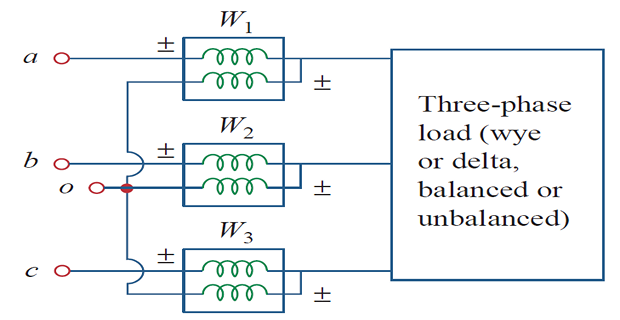
- system where the power factor is constantly changing. well-suited for power measurement in a\[\text{Total power} = P_1 + P_2 + P_3\]
The \(o\) reference or common point arbitrarily selected
For star connection, \(o\) can be neutral point and for delta, it can be any point.
If \(o\) is connected to \(b\), the voltage coil in \(W_2\) reads zero, hence \(W_2=0\).
\(W_2\) is not necessary and 2-watt meters are sufficient to measure total 3-phase power.
Most commonly used for \(3-\phi\) power measurement.
- The two wattmeters must be properly connected to any two phases
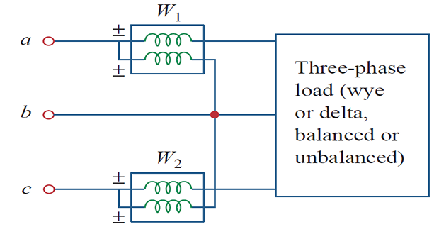
The current coil of each watt meter measures the line current
The respective voltage coil is connected between the line and the third line and measures the line voltage.
\(\pm\) terminal of voltage coil is connected to the line to which the corresponding current coil is connected.
The individual watt-meters no longer read the power taken by any particular phase
- -connected, balanced or unbalanced. - or The total average power absorbed by the load, regardless of whether it is\[\boxed{\mathrm{Total ~3\phi ~power} = P_1 + P_2 \Leftarrow~\text{Algebraic sum}}\]
Consider a balanced \(\mathrm{Y}\) connected load, \(abc\) sequence and load impedance \(\mathbf{Z_Y} = Z_Y\angle \theta\)
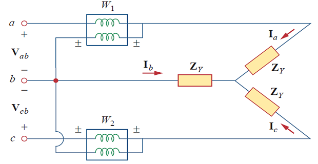
voltage leads the current by \(\theta~\Rightarrow~pf = \cos\theta\)
Recall: line voltage is \(30^{\circ}\) ahead of the corresponding phase voltage
Total phase difference between phase current \(\mathbf{I_a}\) and line voltage \(\mathrm{V_{ab}}\) is \(\theta + 30^{\circ}\)
- are: and Power\[\begin{aligned} P_1 & =\operatorname{Re}\left[\mathbf{V}_{a b} \mathbf{I}_a^*\right]=V_{a b} I_a \cos \left(\theta+30^{\circ}\right)=V_L I_L \cos \left(\theta+30^{\circ}\right) \\ P_2 & =\operatorname{Re}\left[\mathbf{V}_{c b} \mathbf{I}_c^*\right]=V_{c b} I_c \cos \left(\theta-30^{\circ}\right)=V_L I_L \cos \left(\theta-30^{\circ}\right) \\ \end{aligned}\]
- Using trigonometric rules\[\begin{aligned} \cos (A+B) & =\cos A \cos B-\sin A \sin B \\ \cos (A-B) & =\cos A \cos B+\sin A \sin B \end{aligned}\]
- Total real power:\[\begin{aligned} P_1+P_2 & =V_L I_L\left[\cos \left(\theta+30^{\circ}\right)+\cos \left(\theta-30^{\circ}\right)\right] \\ &=V_L I_L\left(\cos \theta \cos 30^{\circ}-\sin \theta \sin 30^{\circ}\right. \\ & \left.\quad+\cos \theta \cos 30^{\circ}+\sin \theta \sin 30^{\circ}\right) \\ &=V_L I_L 2 \cos 30^{\circ} \cos \theta\\ &=\sqrt{3} V_L I_L \cos \theta ~ \Leftarrow 2\cos 30^{\circ} = \sqrt{3} \\ & \boxed{P_T = P_1 + P_2 = \sqrt{3} V_L I_L \cos \theta} \end{aligned}\]
- Similarly:\[\begin{aligned} P_1-P_2= & V_L I_L\left[\cos \left(\theta+30^{\circ}\right)-\cos \left(\theta-30^{\circ}\right)\right] \\ = & V_l I_L\left(\cos \theta \cos 30^{\circ}-\sin \theta \sin 30^{\circ}\right. \\ & \left.\quad-\cos \theta \cos 30^{\circ}-\sin \theta \sin 30^{\circ}\right) \\ = & -V_L I_L 2 \sin 30^{\circ} \sin \theta ~ \Leftarrow 2\sin 30^{\circ} =1 \\ P_2-P_1= & V_L I_L \sin \theta \end{aligned}\]
- Total reactive power:\[\boxed{Q_T = \sqrt{3}\left(P_2-P_1\right)}\]
- Total apparent power:\[S_T = \sqrt{P_T^2+Q_T^2}\]
- To determine pf angle:\[\boxed{\tan\theta = \dfrac{Q_T}{P_T} =\sqrt{3}\cdot \dfrac{P_2-P_1}{P_2+P_1} }\]
From \(\tan\theta ~ \Rightarrow ~\theta ~ \Rightarrow ~\cos\theta = pf\)
2-watt-meter method provides \(P_T\), \(Q_T\), and pf also
- Determine the load characteristics:\[\begin{aligned} \text{If}~ & P_2 = P_1 \Rightarrow~\text{Resistive}\\ \text{If}~ & P_2 > P_1 \Rightarrow~\text{Inductive}\\ \text{If}~ & P_2 < P_1 \Rightarrow~\text{Capacitive} \end{aligned}\]
The two-wattmeter method cannot be used for power measurement in a \(3-\phi\) four-wire system unless neutral current is zero.