Demonstrative Video
Introduction
Electric circuits has led to an evolution from simple to complex circuits.
To handle the complexity, engineers over the years have developed some theorems to simplify circuit analysis.
Such theorems include
Thevenin’s and Norton’s
Superposition
Source transformation
Maximum power transfer
Since these theorems are applicable to linear circuits, we first discuss the concept of circuit linearity
Linearity Property & Linear Circuits
Linearity : property of an element describing a linear relationship between cause and effect.
combination of homogeneity (scaling) + additivity property
- Homogeneity\[\text{Input (excitation)} \times K (\text{constant}) \Rightarrow \text{Output (response)} \times K\]
- Ohm’s law\[V = IR \Rightarrow V\times K = K\times IR\]
- Additivity :\[\begin{aligned} v_1 & = i_1\cdot R\\ v_2 & = i_2 \cdot R\\ v&=\left(i_{1}+i_{2}\right) R=i_{1} R+i_{2} R=v_{1}+v_{2} \end{aligned}\]
Linear circuit : output is linearly related (or directly proportional) to its input.
A resistor is a linear element because the voltage-current relationship satisfies both the homogeneity and the additivity properties
A linear circuit consists of only linear elements, linear dependent sources, and independent sources
Note: \(p=i^{2} R=v^{2} / R\) (making it a quadratic function rather than a linear one), the relationship between power and voltage (or current) is nonlinear.
Therefore, the theorems are not applicable to power.
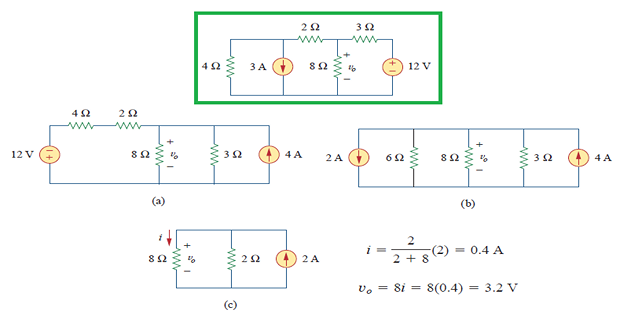
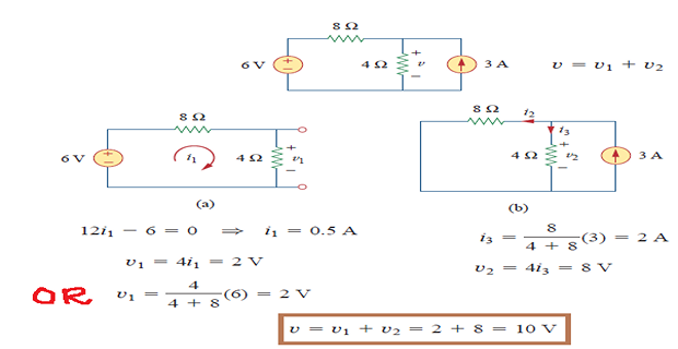
Superposition
The idea of superposition rests on the linearity property
The superposition principle states that the voltage across (or current through) an element in a linear circuit is the algebraic sum of the voltages across (or currents through) that element due to each independent source acting alone.
Helps to analyze a linear circuit with more than one independent source by calculating the contribution of each independent source separately
Two things should be kept in mind:
consider one independent source at a time while all other independent sources are turned off.
replace every voltage source by 0 V (or a short circuit)
every current source by 0 A (or an open circuit)
Dependent sources are left intact because they are controlled by circuit variables.
Steps to Apply Superposition Principle :
Turn off all independent sources except one source. Find the output (voltage or current) due to that active source using the any technique
Repeat step 1 for each of the other independent sources
Find the total contribution by adding algebraically all the contributions due to the independent sources.
Note: superposition is based on linearity so not applicable to the effect on power due to each source.
If the power value is needed, the current through (or voltage across) the element must be calculated first using superposition.
Source Transformation
Based on concept of equivalence recalling that an equivalent circuit is one whose v-i characteristics are identical with the original circuit.
Source transformation is the process of replacing a \(V_s\) in series with \(R\) by \(I_s\) in parallel with \(R\), or vice versa.

Two circuits have same voltage-current relation at terminals a-b
If the sources are turned off, the equivalent resistance at terminals a-b in both circuits is R.
- source transformation requires\[v_{s}=i_{s} R \quad \text { or } \quad i_{s}=\frac{v_{s}}{R}\]
Also applies to dependent sources, provided we carefully handle the dependent variable

Does not affect the remaining part of the circuit
Following points in mind when dealing with source transformation
arrow of the \(I_s\) is directed toward the positive terminal of \(V_s\)
not possible when \(R=0\), which is the case with an ideal voltage source
Similarly, an ideal current source \(R=\infty\) with cannot be replaced by a finite voltage source