Demonstrative Video
Conservation of AC Power
The principle of conservation of power applies to ac as well as to dc circuits
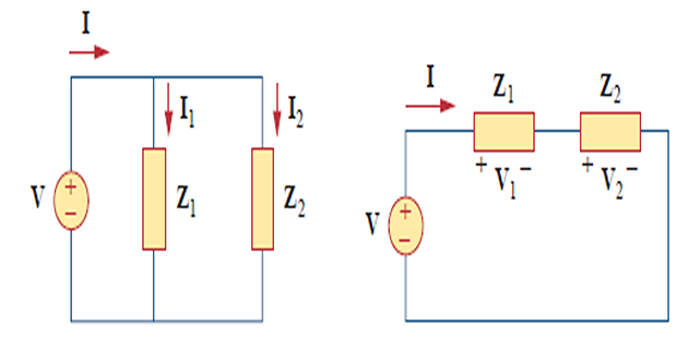
The complex, real, and reactive powers of the sources equal the respective sums of the \(\mathbf{S}\), \(\mathbf{P}\), and \(\mathbf{Q}\) powers of the individual loads.
Problem
Note : \(\mathbf{S}_{s}=\mathbf{S}_{\text {line }}+\mathbf{S}_{L}\), as expected.
We have used the rms values of voltages and currents.
Power Factor Correction
Most domestic loads (washing machines, air conditioners, and refrigerators) and industrial loads ( induction motors) are inductive and operate at a low lagging power factor.
Although the inductive nature of the load cannot be changed, we can increase its power factor.
The process of increasing the PF without altering the voltage or current to the original load is known as power factor correction.
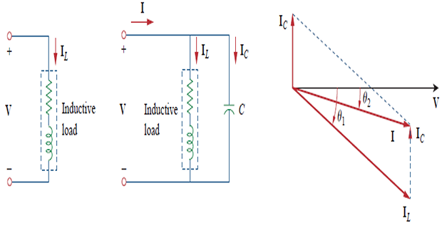
Adding \(C~\Rightarrow\) phase angle reduce from \(\theta_1\) to \(\theta_2~\Rightarrow\) PF \(\uparrow\).
With same \(\mathbf{V}\) current decreases \(\Rightarrow\) less electricity bill.
Problem
When connected to a 120-V (rms), 60-Hz power line, a load absorbs 4 kW at a lagging power factor of 0.8. Find the value of capacitance necessary to raise the pf to 0.95.
- Solution:\[\begin{aligned} \mathrm{pf}=0.8 \Rightarrow \cos \theta_{1}=0.8 \quad \Rightarrow \quad \theta_{1}=36.87^{\circ} \end{aligned}\]
- We obtain the apparent power from the real power and the pf as\[\begin{aligned} S_{1}&=\frac{P}{\cos \theta_{1}}=\frac{4000}{0.8}=5000 \mathrm{VA}\\ Q_{1}&=S_{1} \sin \theta=5000 \sin 36.87=3000 \mathrm{VAR}\\ \cos \theta_{2}&=0.95 \quad \Rightarrow \quad \theta_{2}=18.19^{\circ} \end{aligned}\]
- has not changed. But the apparent power has changed; its new value is , The real power is raised to When the\[S_{2}=\frac{P}{\cos \theta_{2}}=\frac{4000}{0.95}=4210.5 \mathrm{VA}\]
- The new reactive power is\[Q_{2}=S_{2} \sin \theta_{2}=1314.4 \mathrm{VAR}\]
The difference between the new and old reactive powers is due to the parallel addition of the capacitor to the load.
- \[Q_{C}=Q_{1}-Q_{2}=3000-1314.4=1685.6 \mathrm{VAR}\]The reactive power due to the capacitor is\[C=\frac{Q_{C}}{\omega V_{\mathrm{rms}}^{2}}=\frac{1685.6}{2 \pi \times 60 \times 120^{2}}=310.5 \mu \mathrm{F}\]