Demonstrative Video
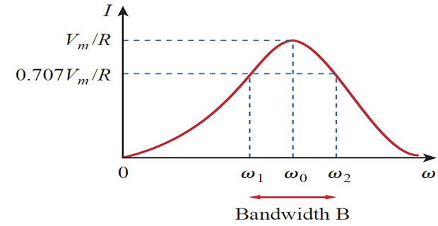
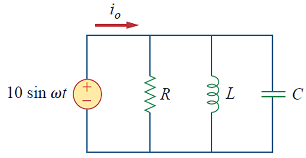
PARALLEL RESONANCE

also called Tank circuit

\[\begin{aligned}
\mathbf{Y}&=H(\omega) =\frac{\mathbf{I}}{\mathbf{V}}\\
\mathbf{Y} & =\frac{1}{R}+j\left(\omega C-\frac{1}{\omega L}\right)
\\
& \omega C-\frac{1}{\omega L}=0 \\
\omega_{0} & =\frac{1}{\sqrt{L C}} \operatorname{rad} / \mathrm{s}
\\
\end{aligned}\]
- \[\begin{aligned} \omega_{1} &=\omega_{0} \sqrt{1+\left(\frac{1}{2 Q}\right)^{2}}-\frac{\omega_{0}}{2 Q}, \quad \omega_{2}=\omega_{0} \sqrt{1+\left(\frac{1}{2 Q}\right)^{2}}+\frac{\omega_{0}}{2 Q} \end{aligned}\]Half-power frequencies
- \[\begin{aligned} \omega_{1} & \simeq \omega_{0}-\frac{B}{2}, \quad \omega_{2} \simeq \omega_{0}+\frac{B}{2} \end{aligned}\]circuits For high
Resonant RLC circuits
| Characteristic | Series circuit | Parallel circuit |
|---|---|---|
| Resonant freq, \(\omega_{0}\) | \(\dfrac{1}{\sqrt{L C}}\) | \(\dfrac{1}{\sqrt{L C}}\) |
| Quality factor, Q | \(\dfrac{\omega_{0} L}{R} \text { or } \dfrac{1}{\omega_{0} R C}\) | \(\dfrac{R}{\omega_{0} L} \text { or } \omega_{0} R C\) |
| Bandwidth, B | \(\dfrac{\omega_{0}}{Q}\) | \(\dfrac{\omega_{0}}{Q}\) |
| Half-power freq., \(\omega_{1,2}\) | \(\omega_{0} \sqrt{1+\left(\dfrac{1}{2 Q}\right)^{2}} \pm \dfrac{\omega_{0}}{2 Q}\) | \(\omega_{0} \sqrt{1+\left(\dfrac{1}{2 Q}\right)^{2}} \pm \dfrac{\omega_{0}}{2 Q}\) |
| For \(Q \geq 10, \omega_{1}, \omega_{2}\) | \(\omega_{0} \pm \dfrac{B}{2}\) | \(\omega_{0} \pm \dfrac{B}{2}\) |
Problem
Let \(R=8~k \Omega\), \(L=0.2~\mathrm{mH}\), and \(C=8~\mathrm{\mu F}\). calculate
\(\omega_{0,1,2}, ~Q, ~B\)
power dissipated at \(\omega_{0,1,2}\)

\[\begin{aligned}
\omega_0 & = \dfrac{1}{\sqrt{LC}} = 25~\mathrm{krad/s} \\
Q & = \dfrac{R}{\omega_0 L} = 1600 \\
B & = \dfrac{\omega_0}{Q} = 15.625 ~\mathrm{rad/s} \\
\omega_1 & = \omega_0 - \dfrac{B}{2} = 24,992~\mathrm{rad/s} \\
\omega_2 & = \omega_0 + \dfrac{B}{2} = 25,008~\mathrm{rad/s} \\
\end{aligned}\]