Demonstrative Video
Node-Voltage Analysis
We cannot solve complicated circuit simply by combining resistances in series and parallel because no series or parallel combination of resistances exists in the circuit directly.
Furthermore, the voltage-division and current-division principles cannot be applied every time.
Steps involve in node-voltage analysis:
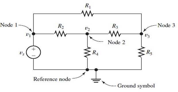
Selecting the Reference Node
Assigning Node Voltages
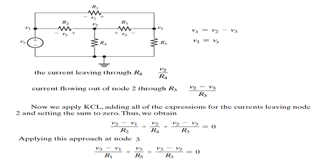
Finding Element Voltages in Terms of the Node Voltages
Writing KCL Equations in Terms of the Node Voltages
Introduction
Two powerful techniques to solve linear circuits forming set of simultaneous equations that are then solved to obtain the required values of current or voltage.
Nodal analysis : systematic application of KCL
Mesh analysis : systematic application of KVL
Nodal analysis
Procedure for analyzing circuits using node voltages as the circuit variables.
Choosing node voltages instead of element voltages as circuit variables is convenient and reduces the number of equations one must solve simultaneously.
First we will assume circuits do not contain voltage sources.
Steps to Determine Node Voltages (without voltage sources):
Select a node as the reference node.
Assign voltages \(v_{1}\), \(v_{2}, \ldots, v_{n-1}\) to the remaining \(n-1\) nodes referenced with respect to the reference node.
Apply KCL to each of the \(n-1\) non-reference nodes.
Use Ohm’s law to express the branch currents in terms of node voltages.
Solve the resulting simultaneous equations to obtain the unknown node voltages.
Steps for nodal analysis
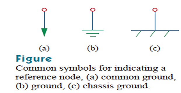
Step-1 : Choose reference or ground node, assuming to have zero potential.
Step-2 : Assign voltage designations to non-reference nodes
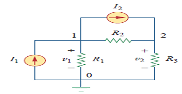
- \[\begin{aligned} \text{At node 1},& \quad I_{1}=I_{2}+i_{1}+i_{2}\\ \text{At node 2}, &\quad I_{2}+i_{2}=i_{3} \end{aligned}\]Step-3 :
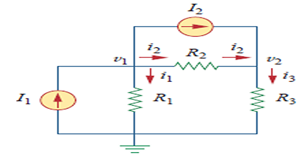
Simultaneous equations may be solved using calculators or with software packages such as MATLAB, Mathcad, Maple, etc.
CRAMER’s RULE:
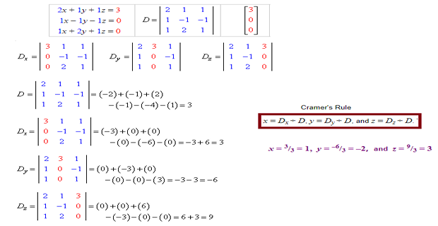
Nodal Analysis with Voltage Sources
Consider the following two possibilities:
Case-1 : voltage source is connected between the reference node and a non-reference node, we simply set the voltage at the nonreference node equal to the voltage of the voltage source
Case-2 : If the voltage source (dependent or independent) is connected between two nonreference nodes, the two nonreference nodes form a generalized node or supernode; we apply both KCL and KVL to determine the node voltages.
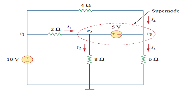
nodes 2 and 3 form a supernode. ( could have more than two nodes also)
Previously discussed steps remain same except supernodes are treated differently, Why?
Nodal analysis requires current through each element for KCL but the current through voltage source is not known in advance
- \[\begin{aligned} i_{1}+i_{4} &=i_{2}+i_{3} \\ \frac{v_{1}-v_{2}}{2}+\frac{v_{1}-v_{3}}{4} &=\frac{v_{2}-0}{8}+\frac{v_{3}-0}{6} \end{aligned}\]However, KCL must be satisfied at a supernode like any other node.
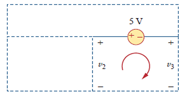
- \[-v_{2}+5+v_{3}=0 \quad \Rightarrow \quad v_{2}-v_{3}=5\]Applying Kirchhoff’s voltage law to the supernode
Properties of a supernode:
The voltage source inside the supernode provides a constraint equation needed to solve for the node voltages.
A supernode has no voltage of its own.
A supernode requires the application of both KCL and KVL.
Mesh Analysis
Using mesh currents instead of element currents as circuit variables is convenient and reduces the number of equations that must be solved simultaneously
A mesh is a loop that does not contain any other loop within it.
Nodal analysis applies KCL to find unknown voltages in a given circuit, while mesh analysis applies KVL to find unknown currents
Mesh analysis is not quite as general as nodal analysis because it is only applicable to a circuit that is planar.
A planar circuit is one that can be drawn in a plane with no branches crossing one another; otherwise it is nonplanar.
A circuit may have crossing branches and still be planar if it can be redrawn such that it has no crossing branches
Steps to Determine Mesh Currents:
1. Assign mesh currents \(i_{1}, i_{2}, \ldots, i_{n}\) to the \(n\) meshes.
Apply KVL to each of the \(n\) meshes. Use Ohm’s law to express the voltages in terms of the mesh currents.
Solve the resulting \(n\) simultaneous equations to get the mesh currents.
- \[\begin{aligned} -V_{1}+R_{1} i_{1}+R_{3}\left(i_{1}-i_{2}\right)&=0 \\ \Rightarrow \left(R_{1}+R_{3}\right) i_{1}-R_{3} i_{2}&=V_{1} \end{aligned}\]KVL in mesh-1:
- \[\begin{aligned} R_{2} i_{2}+V_{2}+R_{3}\left(i_{2}-i_{1}\right)&=0 \\ \Rightarrow -R_{3} i_{1}+\left(R_{2}+R_{3}\right) i_{2}&=-V_{2} \end{aligned}\]KVL in mesh-2
Mesh Analysis with Current Sources
Mesh analysis to circuits containing current sources (dependent or independent)
A supermesh results when two meshes have a (dependent or independent) current source in common.
Case-1 : current source exists only in one mesh
\[-10+4 i_{1}+6\left(i_{1}-i_{2}\right)=0 \Rightarrow \quad i_{1}=-2 \mathrm{~A}\]Case-2 : current source exists between two meshes
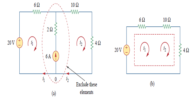
- \[\begin{aligned} -20+6 i_{1}+10 i_{2}+4 i_{2} &=0 \\ \Rightarrow 6 i_{1}+14 i_{2} &=20 \end{aligned}\]Applying KVL:
- \[\begin{gathered} i_{2}=i_{1}+6 \\ i_{1}=-3.2 \mathrm{~A}, \quad i_{2}=2.8 \mathrm{~A} \end{gathered}\]Applying KCL:
Properties of Super-mesh:
The current source in the supermesh provides the constraint equation necessary to solve for the mesh currents.
A supermesh has no current of its own.
A supermesh requires the application of both KVL and KCL.
Nodal and Mesh Analyses by Inspection
Shortcut approach based on mere inspection of a circuit
When all sources in a circuit are independent current sources, do not need to apply KCL or KVL to each node to obtain the equations
We can obtain the equations by mere inspection of the circuit.
Nodal analysis by Inspection
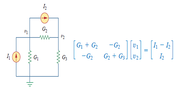
- \[\left[\begin{array}{cccc} G_{11} & G_{12} & \ldots & G_{1 N} \\ G_{21} & G_{22} & \ldots & G_{2 N} \\ \vdots & \vdots & \vdots & \vdots \\ G_{N 1} & G_{N 2} & \ldots & G_{N N} \end{array}\right]\left[\begin{array}{c} v_{1} \\ v_{2} \\ \vdots \\ v_{N} \end{array}\right]=\left[\begin{array}{c} i_{1} \\ i_{2} \\ \vdots \\ i_{N} \end{array}\right] \quad \Rightarrow \mathbf{G v}=\mathbf{i}\]\(\begin{aligned} G_{k k}=& \text { Sum of the conductances connected to node } k \\ G_{k j}=& G_{j k}=\text { Negative of the sum of the conductances directly } \\ & \text { connecting nodes } k \text { and } j, k \neq j \\ v_{k}=& \text { Unknown voltage at node } k \\ i_{k}=& \text { Sum of all independent current sources directly connected }\\ & \text{to node $k$, with currents entering the node treated as positive} \end{aligned}\)In general, if a circuit with independent current sources has N nonreference nodes, the node-voltage equations can be written in terms of the conductances as
- Example:
Mesh analysis by Inspection
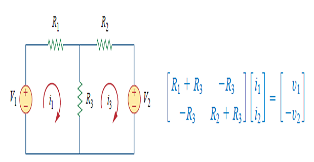
In general, if the circuit has N meshes, the mesh-current equations can be expressed in terms of the resistances as
\(\left[\begin{array}{cccc}R_{11} & R_{12} & \ldots & R_{1 N} \\ R_{21} & R_{22} & \ldots & R_{2 N} \\ \vdots & \vdots & \vdots & \vdots \\ R_{N 1} & R_{N 2} & \ldots & R_{N N}\end{array}\right]\left[\begin{array}{c}i_{1} \\ i_{2} \\ \vdots \\ i_{N}\end{array}\right]=\left[\begin{array}{c}v_{1} \\ v_{2} \\ \vdots \\ v_{N}\end{array}\right] \Rightarrow \mathbf{R i}=\mathbf{v}\) \[\begin{aligned} R_{k k}&= \text{Sum of the resistances in mesh} k \\ R_{k j}=& R_{j k}=\text { Negative of the sum of the resistances in common } \\ & \text { with meshes } k \text { and } j, k \neq j\\ i_{k}&= \text{Unknown mesh current for mesh $k$ in the clockwise direction}\\ v_{k}&=\text{ Sum taken clockwise of all independent voltage sources}\\ &\text{ in mesh $k$, with voltage rise treated as positive} \end{aligned}\]
- Example:
Choosing : Nodal Vs Mesh Analysis
Networks that contain many series-connected elements, voltage sources, or supermeshes are more suitable for mesh analysis.
Networks with parallel-connected elements, current sources, or supernodes are more suitable for nodal analysis.
A circuit with fewer nodes than meshes is better analyzed using nodal analysis, while a circuit with fewer meshes than nodes is better analyzed using mesh analysis.
If node voltages are required, it may be expedient to apply nodal analysis.
If branch or mesh currents are required, it may be better to use mesh analysis