Demonstrative Video
Power in AC Circuits
The most common form of electric power is 50- or 60-Hz ac power.
The choice of ac over dc allowed high-voltage power transmission from the power generating plant to the consumer.
Instantaneous Power : \(p(t)\) absorbed by an element is the product of the instantaneous voltage \(v(t)\) across the element and the instantaneous current \(i(t)\) through it.
Instantaneous power has two parts.
The first part is constant or time independent. Its value depends on the phase difference between the voltage and the current.
The second part is a sinusoidal function whose frequency is \(2\omega\)
\(p(t)\) is periodic with \(T=2\pi/\omega\) is the period
When \(p(t)\) is positive, power is absorbed by the circuit.
When \(p(t)\) is negative, power is absorbed by the source; power is transferred from the circuit to the source.
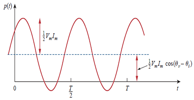
This is because of the storage elements (L or C) in the circuit.
\(p(t)\) changes with time and difficult to measure, hence average power is more convenient.
Watt-meter for measuring power responds to average power.
Average Power
- Average of the instantaneous power over one period.\[\begin{aligned} P=& \frac{1}{T} \int_{0}^{T} p(t) d t \\ P=& \frac{1}{T} \int_{0}^{T} \frac{1}{2} V_{m} I_{m} \cos \left(\theta_{v}-\theta_{i}\right) d t +\frac{1}{T} \int_{0}^{T} \frac{1}{2} V_{m} I_{m} \cos \left(2 \omega t+\theta_{v}+\theta_{i}\right) d t \\ =& \frac{1}{2} V_{m} I_{m} \cos \left(\theta_{v}-\theta_{i}\right) \frac{1}{T} \int_{0}^{T} d t +\frac{1}{2} V_{m} I_{m} \frac{1}{T} \int_{0}^{T} \cos \left(2 \omega t+\theta_{v}+\theta_{i}\right) d t \end{aligned}\]
The first integrand is constant and second integrand is a sinusoid.
The average of a sinusoid over its period is zero because the area under the sinusoid during a positive half-cycle is cancelled by the area under it during the following negative half-cycle.
\(p(t)\) is time-varying while \(P\) does not depend on time
\(p(t)\) depends on \(v(t)\) and \(i(t)\) in time-domain
- \(P\)\[\begin{aligned} &\mathbf{V}=V_{m} \angle \theta_{v} \text { and } \mathbf{I}=I_{m} \angle \theta_{i} \\ &\frac{1}{2} \mathbf{V I}^{*}= \frac{1}{2} V_{m} I_{m} \angle \theta_{v}-\theta_{i} \\ &= \frac{1}{2} V_{m} I_{m}\left[\cos \left(\theta_{v}-\theta_{i}\right)+j \sin \left(\theta_{v}-\theta_{i}\right)\right]\\ &\boxed{P=\frac{1}{2} \operatorname{Re}\left[\mathbf{V I}^{*}\right]= \frac{1}{2} V_{m} I_{m} \cos( \theta_{v}-\theta_{i} ) } \end{aligned}\]
-
\(|\mathrm{I}|^2 = \mathrm{I} \times \mathrm{I^{\ast}}\) Purely resistive circuit:\[P = \dfrac{1}{2}V_mI_m = \dfrac{1}{2} I_m^2R=\dfrac{1}{2}|\mathbf{I}|^2R\]
- Purely reactive circuit:\[P = \dfrac{1}{2}V_mI_m \cos 90^{\circ} = 0\]
A resistive load (\(R\) ) absorbs power at all times, while a reactive load (\(L\) or \(C\) ) absorbs zero average power.
Problem
Given \(v(t)=120 \cos \left(377 t+45^{\circ}\right) \mathrm{V} \quad\) and \(\quad i(t)=10 \cos \left(377 t-10^{\circ}\right) \mathrm{A}\) find the instantaneous power and the average power absorbed by the passive linear network
Solution:
Maximum Average Power Transfer
Maximum Power Transfer in DC Circuits \(\Rightarrow~R_L = R_{TH}\)
- For AC Circuits:\[\begin{aligned} \mathbf{Z}_{\mathrm{Th}} &=R_{\mathrm{Th}}+j X_{\mathrm{Th}} \qquad \mathbf{Z}_{L} =R_{L}+j X_{L} \\ \mathbf{I} &=\frac{\mathbf{V}_{\mathrm{Th}}}{\mathbf{Z}_{\mathrm{Th}}+\mathbf{Z}_{L}}=\frac{\mathbf{V}_{\mathrm{Th}}}{\left(R_{\mathrm{Th}}+j X_{\mathrm{Th}}\right)+\left(R_{L}+j X_{L}\right)} \\ P &=\frac{1}{2}|\mathbf{I}|^{2} R_{L}=\frac{\left|\mathbf{V}_{\mathrm{Th}}\right|^{2} R_{L} / 2}{\left(R_{\mathrm{Th}}+R_{L}\right)^{2}+\left(X_{\mathrm{Th}}+X_{L}\right)^{2}} \end{aligned}\]
- . must be equal to the complex conjugate of For MPT,\[\begin{aligned} &\boxed{P_{\max } =\frac{\left|\mathbf{V}_{\mathrm{Th}}\right|^{2}}{8 R_{\mathrm{Th}}}} \qquad R_{L} =\sqrt{R_{\mathrm{Th}}^{2}+X_{\mathrm{Th}}^{2}}=\left|\mathbf{Z}_{\mathrm{Th}}\right|~\Leftarrow ~(\text{for}~X_L=0) \end{aligned}\]
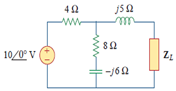
Problem
Determine \(Z_L\) that maximizes the
average power drawn from the circuit. What is \(P_{\text{max}}\)?
Effective or RMS Value
The idea of effective value arises from the need to measure the effectiveness of a voltage or current source in delivering power to a resistive load.
The effective value of a periodic current is the dc current that delivers the same average power to a resistor as the periodic current.
When a sinusoidal voltage or current is specified, it is often in terms of its maximum (or peak) value or its rms value, since its average value is zero.
The power industries specify phasor magnitudes in terms of their rms values rather than peak values.
For instance, the 110 V available at every household is the rms value of the voltage from the power company.
It is convenient in power analysis to express voltage and current in their rms values.
Also, analog voltmeters and ammeters are designed to read directly the rms value of voltage and current, respectively.
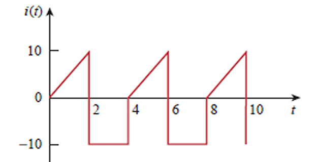
Problem-1
Determine the rms value of the current waveform If the current is
passed through a \(2~\Omega\) resistor,
find the average power absorbed by the resistor.
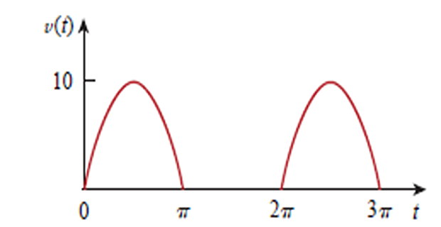
Problem-2
The waveform shown is a half-wave rectified sine wave. Find the rms
value and the amount of average power dissipated in \(10~\Omega\) resistor.
Apparent Power and Power Factor
The average power is a product of two terms.
The product \(V_{\mathrm{rms}} I_{\mathrm{rms}}\) is known as the apparent power, S.
The factor \(\cos(\theta_v-\theta_i)\) is called the power factor (pf).
The apparent power is so called because it seems apparent that the power should be the voltage-current product, by analogy with dc resistive circuits.
It is measured in volt-amperes or VA to distinguish it from the average or real power, which is measured in watts.
- , whose value ranges between zero and unity. The power factor is\[\mathrm{pf} = \dfrac{P}{S} = \cos(\theta_{v}-\theta_{i})\]
The angle \((\theta_{v}-\theta_{i})\) is called the power factor angle.
For purely resistive load \(pf=1\) and for purely reactive load \(pf=0\). In between it is either lagging or leading pf.
The power factor angle is equal to the angle of the load impedance if \(\mathbf{V}\) is the voltage across the load and \(\mathbf{I}\) is the current through it.
Problem-1
A series-connected load draws a current \(i(t)=4 \cos \left(100 \pi t+10^{\circ}\right) \mathrm{A}\) when the applied voltage is \(v(t)=120 \cos \left(100 \pi t-20^{\circ}\right) \mathrm{V}\). Find the apparent power and the power factor of the load. Determine the element values that form the series-connected load.
- Solution:\[S=V_{\mathrm{rms}} I_{\mathrm{rms}}=\frac{120}{\sqrt{2}} \frac{4}{\sqrt{2}}=240 \mathrm{VA}\]
- The power factor is\[\mathrm{pf}=\cos \left(\theta_{v}-\theta_{i}\right)=\cos \left(-20^{\circ}-10^{\circ}\right)=0.866 \quad \text { (leading) }\]
- The pf is leading because the current leads the voltage. The pf may also be obtained from the load impedance.\[\begin{aligned} \mathbf{Z}=\frac{\mathbf{V}}{\mathbf{I}} &=\frac{120 \angle -20^{\circ}}{4 \angle 10^{\circ}}=30 \angle -30^{\circ}=25.98-j 15 \Omega \\ \mathrm{pf} &=\cos \left(-30^{\circ}\right)=0.866 \quad \text { (leading) } \end{aligned}\]
- \[X_{C}=-15=-\frac{1}{\omega C}\]resistor in series with a capacitor with can be modeled by a The load impedance\[C=\frac{1}{15 \omega}=\frac{1}{15 \times 100 \pi}=212.2 \mu \mathrm{F}\]