Demonstrative Video
Electrical Network
Interconnection of electrical components like resistors, inductors, semiconductors devices, TFs and sources of e.m.f. is called as a network.
A network does not require to have a closed path, the open circuit also can be called as a network.
The network containing closed loop provides return path for the current.
A network may contain one or more circuit elements.
It has two or more terminals for making connection with other circuits.
Classification of Electrical Network
The behaviour of the entire network depends on the behaviour and characteristics of its elements.
Based on such characteristics electrical network can be classified :
Linear Network
Non linear Network
Bilateral Network
Unilateral Network
Active Network
Passive Network
Lumped Network
Distributed Network
Linear Network
elements like resistances, inductances and capacitances are always constant irrespective of the change in time, voltage, temperature etc.
The Ohm’s law can be applied to such network.
The mathematical equations are obtained by using the law of superposition.
Non linear Network
parameters change their values with change in time, temperature, voltage etc.
The Ohm’s law may not be applied to such network.
Such network does not follow the law of superposition.
Bilateral Network
characteristics is same irrespective of the direction of current through various elements of it.
Network consisting only resistances is good example
Unilateral Network
behaviour is dependent on the direction of the current through various elements
Circuit consisting diodes, which allows flow of current only in one direction is good example
Active Network
A circuit which contains a source of energy.
An energy source may be a voltage or current source.
Passive Network
A circuit which contains no energy source.
There are two forms of circuits in which two types of voltages are used.
One alternating i.e. ac. while second is direct i.e. d.c.
Lumped Network
network elements are physically separable is known as lumped network.
Most of the electric networks are lumped in nature.
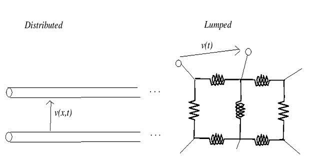
Distributed Network
circuit elements like resistance, inductance etc. cannot be physically separable for analysis purposes.
The best example is a transmission line where resistance, inductance and capacitance of a transmission line are distributed all along its length and cannot be shown as a separate elements, any where in the circuit.
One port and Two port Network
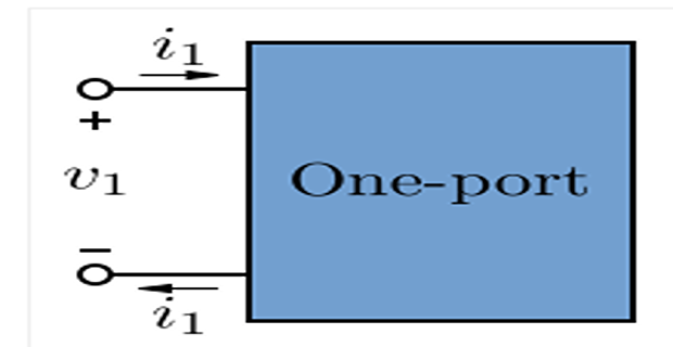
One port network
has one pair of terminal
helps to reduce the complexity of circuit analysis
In many common electronic devices and circuit blocks such as transistors, amplifiers, electronic filters, and transformers are analysed in terms of ports.
A series, parallel combination of resistors and capacitors are example of one port network.
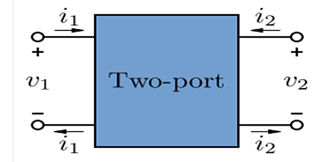
Two port network
The network having two pairs of terminal is called a two port network.
An amplifier, attenuator, filter, transformer are examples
Lumped Vs Distributed Systems
A lumped system is one in which the dependent variables of interest are a function of time alone. In general, this will mean solving a set of ordinary differential equations (ODEs)
A distributed system is one in which all dependent variables are functions of time and one or more spatial variables. In this case, we will be solving partial differential equations (PDEs)
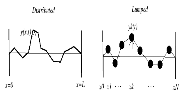
Distributed system consisting of an infinitely thin string, supported at both ends; the dependent variable, the vertical position of the string \(y(x,t)\) is indexed continuously in both space and time.
Lumped system , a series of beads connected by massless string segments, constrained to move vertically, can be thought of as a lumped system, perhaps an approximation to the continuous string.
The importance of lumped approximations to distributed systems enables one to cut computational costs by solving ODEs at a few points, rather than a full PDE (generally much more costly)
Lumped and Distributed Elements
Lumped Elements:
Size of an element is smaller than the wavelength of the applied signals
Generally, the size is less than 1/20 times the operating guided wavelength.
Effect of wave propagation can be neglected
Physical dimensions of lumped elements make it so that signals do not vary over the interconnects interfacing them.
Only minimal phase differences between the input and output signals
Distributed Elements:
Physical dimension is comparable with the operating wavelength.
Distributed over lengths in a circuit.
When conventional lumped elements are difficult to implement at certain frequencies, distributed-elements are used instead.
Perform the same functions as lumped elements, but the signals vary along the lines and between the elements.
These signals undergo considerable phase change across various points within the distributed elements.
Signal transit time cannot be neglected in distributed elements.
Elements of an Electrical Circuit
Elements of an electric circuit can be interconnected in several ways, we need to understand some basic concepts of network topology.
While network is an interconnection of elements or devices, whereas a circuit is a network providing one or more closed paths
An electric circuit based on three concepts, namely, node, branch and loop.
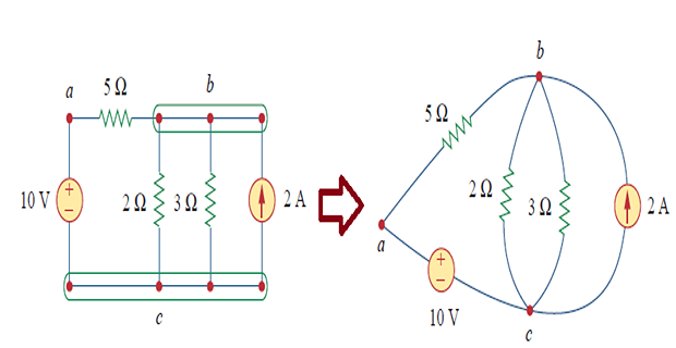
Branch : represents a single element such as a voltage source or a resistor.
In other words, a branch represents any two-terminal element
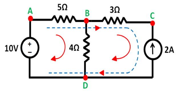
e.g.: 5 branches, 10-V + 2-A + three resistors
Node : point of connection between two or more branches
node is usually indicated by a dot in a circuit
If a short circuit (a connecting wire) connects two nodes, the two nodes constitute a single node.
e.g. 3 nodes: a,b, and c
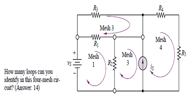
Loop : any closed path formed by starting at a node, passing through a set of nodes, and returning to the starting node without passing through any node more than once.
A loop is said to be independent if it contains at least one branch which is not a part of any other independent loop.
Independent loops or paths result in independent sets of equations.
- independent loops will satisfy the fundamental theorem of network topology: nodes, and branches, A network with\[\boxed{b = l+n-1}\]
Two or more elements are in series if they exclusively share a single node and consequently carry the same current.
Two or more elements are in parallel if they are connected to the same two nodes and consequently have the same voltage across them.
Mesh : closed path in the circuit, which does not contain any other close path inside it
Note: All Mesh are loops but not all the loops are Mesh.