Demonstrative Video
Introduction
Previously, we studied circuits composed of resistances and sources.
Now, we discuss two additional circuit elements: inductors and capacitors.
Resistors convert electrical energy into heat
Inductors and capacitors are energy-storage elements.
They can store energy and later return it to the circuit.
They do not generate energy—only the energy that has been put into these elements can be extracted.
Thus, like resistors, they are said to be passive elements.
EMFT is the basic approach to the study of the effects of electrical charge.
Circuit theory is a simplification of field theory that is much easier to apply.
Capacitance is the circuit property that accounts for energy stored in electric fields.
Inductance accounts for energy stored in magnetic fields.
The voltage across an ideal inductor is proportional to the time derivative of the current.
The voltage across an ideal capacitor is proportional to the time integral of the current.
Mutual inductance is the circuit property that accounts for magnetic fields that are mutual to several inductors.
Mutual inductance forms the basis for transformers, which are critical to the transmission of electrical power over long distances.
Several types of transducers are based on inductance and capacitance
Capacitance
A capacitor is a passive element designed to store energy in its electric field.
Capacitors are constructed by separating two sheets of conductor, which is usually metallic, by a thin layer of insulating material.
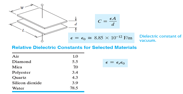
In a parallel-plate capacitor (\(C=\epsilon A/d\)), the sheets are flat and parallel.
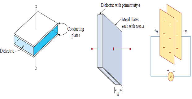
The insulating material between the plates, called a dielectric, can be air, polyester, polypropylene, mica, or a variety of other materials.
Capacitors are used extensively in electronics, communications, computers, and power systems.
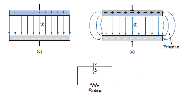
Capacitance of the Parallel-Plate Capacitor
Capacitance & Fluid-Flow Analogy
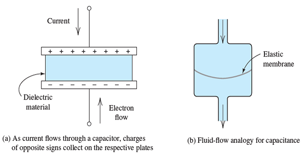
Suppose current in the capacitor flows downward.
Current consists of moving electrons, and conventional current flowing downward represents electrons actually moving upward.
As electrons move upward, they collect on the lower plate of the capacitor.
Thus, the lower plate accumulates a net negative charge that produces an electric field in the dielectric.
This electric field forces electrons to leave the upper plate at the same rate that they accumulate on the lower plate.
Therefore, current appears to flow through the capacitor.
As the charge builds up, voltage appears across the capacitor.
We say that the charge accumulated on one plate is stored in the capacitor.
However, the total charge on both plates is always zero, because positive charge on one plate is balanced by negative charge of equal magnitude on the other plate.
In terms of the fluid-flow analogy, a capacitor represents a reservoir with an elastic membrane separating the inlet and outlet.
As the fluid flows into the inlet, the membrane is stretched, creating a force (analogous to capacitor voltage) that opposes further flow.
The displaced fluid volume starting from the un-stretched membrane position is analogous to the charge stored on one plate of the capacitor.
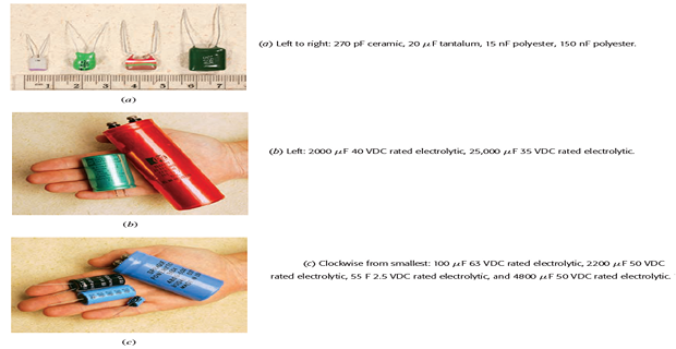
Commercial available capacitors
Important properties of a capacitor
- When the voltage across a capacitor is not changing with time (i.e., dc voltage), the current through the capacitor is zero. Thus,\[\text{A capacitor is an open circuit to dc.}\]
However, if a battery (dc voltage) is connected across a capacitor, the capacitor charges.
The voltage on a capacitor cannot change abruptly.
The ideal capacitor does not dissipate energy. It takes power from the circuit when storing energy in its field and returns previously stored energy when delivering power to the circuit.
A real, non-ideal capacitor has a parallel-model leakage resistance. The leakage resistance may be as high as 100 M\(\Omega\) and can be neglected in practical applications.
Stored Charge & Current in Terms of Voltage
- is proportional to the voltage between the plates: In an ideal capacitor, the stored charge\[\boxed{q = C\cdot v}\]
The constant of proportionality is the capacitance \(C\), which has units of farads (F), equivalent to coulombs per volt.
Recall that current is the time rate of flow of charge
\[i = \dfrac{dq}{dt} = \dfrac{d(Cv)}{dt} = C\dfrac{dv}{dt}\]Capacitance is not a function of time.
\(v\uparrow \Rightarrow i\) flows through \(C\) and \(q\) accumulates on each plate.
If \(v\) remains constant, \(q\) is constant and \(i=0\).
Thus, a \(C\) appears to be an open-circuit for a steady dc voltage.
Voltage in Terms of Current
Computation of \(q\) and \(v\) for known \(i\) through \(C\)
Stored Energy in a Capacitor
Suppose \(C\) that initially has \(v(t_0) = 0\).
Then the initial stored electrical energy is zero, and we say that the capacitor is uncharged
Capacitances in Series and Parallel
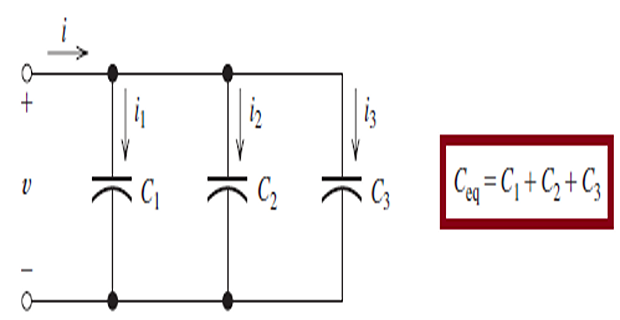
- Capacitances in Parallel
- Capacitances in Series

- Voltage distribution\[v=v_{1}+v_{2}+v_{3}+\cdots+v_{N}\]
But \(v_{k}=\dfrac{1}{C_{k}} \int_{t_{0}}^{t} i(t) d t+v_{k}\left(t_{0}\right) .\)
- Therefore,\[\begin{aligned} v &=\frac{1}{C_{1}} \int_{t_{0}}^{t} i(t) d t+v_{1}\left(t_{0}\right)+\frac{1}{C_{2}} \int_{t_{0}}^{t} i(t) d t+v_{2}\left(t_{0}\right)+\cdots+\\ &+\frac{1}{C_{N}} \int_{t_{0}}^{t} i(t) d t+v_{N}\left(t_{0}\right) \\ &=\left(\frac{1}{C_{1}}+\frac{1}{C_{2}}+\cdots+\frac{1}{C_{N}}\right) \int_{t_{0}}^{t} i(t) d t+v_{1}\left(t_{0}\right)+v_{2}\left(t_{0}\right)+\cdots+v_{N}\left(t_{0}\right) \\ &=\frac{1}{C_{\mathrm{eq}}} \int_{t_{0}}^{t} i(t) d t+v\left(t_{0}\right) \end{aligned}\]
- where\[\frac{1}{C_{\mathrm{eq}}}=\frac{1}{C_{1}}+\frac{1}{C_{2}}+\frac{1}{C_{3}}+\cdots+\frac{1}{C_{N}}\]