Demonstrative Video
SECTION 01
Demonstrative Video
SECTION 01
Power in a Balanced System
\[\begin{aligned}
v_{A N}& =\sqrt{2} V_{p} \cos \omega t \\
v_{B N}&=\sqrt{2} V_{p} \cos \left(\omega
t-120^{\circ}\right) \\
v_{C N}&=\sqrt{2} V_{p} \cos \left(\omega
t+120^{\circ}\right)
\end{aligned}\]
\[\begin{aligned}
p&=p_{a}+p_{b}+p_{c}=v_{A N} i_{a}+v_{B N} i_{b}+v_{C N} i_{c}
\\
&=2 V_{p} I_{p}\left[\cos \omega t \cos (\omega t-\theta)+\cos
\left(\omega t-120^{\circ}\right) \cos \left(\omega
t-\theta-120^{\circ}\right)\right.
+\\
& ~~ \qquad \left.\cos \left(\omega t+120^{\circ}\right) \cos
\left(\omega t-\theta+120^{\circ}\right)\right] \\
=&V_{p} I_{p}\left[3 \cos \theta+\cos (2 \omega t-\theta)+\cos
\left(2 \omega t-\theta-240^{\circ}\right)+\cos \left(2 \omega
t-\theta+240^{\circ}\right)\right] \\
=&V_{p} I_{p}[3 \cos \theta+\cos \alpha+\cos \alpha \cos
240^{\circ}+\sin \alpha \sin 240^{\circ}+\cos \alpha \cos 240^{\circ}\\
& \qquad \qquad -\sin \alpha \sin 240^{\circ}] \\
=&V_{p} I_{p}\left[3 \cos \theta+\cos
\alpha+2\left(-\frac{1}{2}\right) \cos \alpha\right]=\boxed{3 V_{p}
I_{p} \cos \theta}~~\boxed{\alpha = 2\omega t - \theta }
\end{aligned}\]
Important Points:
Thus the total instantaneous power in a balanced \(3-\phi\) system is constant—it does not change with time as the instantaneous power of each phase does.
This result is true whether the load is Y- or \(\Delta\)-connected.
This is one important reason for using a three-phase system to generate and distribute power.
\[\begin{aligned}
P_{p} &=V_{p} I_{p} \cos \theta \\
Q_{p} &=V_{p} I_{p} \sin \theta \\
S_{p} &=V_{p} I_{p} \\
\mathbf{S}_{p} &=P_{p}+j Q_{p}=\mathbf{V}_{p}
\mathbf{I}_{p}^{*} \\
P &=P_{a}+P_{b}+P_{c} \\
&=3 P_{p} \\
&=3 V_{p} I_{p} \cos \theta=\sqrt{3} V_{L} I_{L} \cos
\theta
\end{aligned}\]
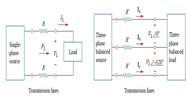
\[\begin{aligned}
P_{\text {loss }} &=2 I_{L}^{2} R=2 R
\frac{P_{L}^{2}}{V_{L}^{2}}\\
P_{\text {loss }}^{\prime}&=3\left(I_{L}^{\prime}\right)^{2}
R^{\prime}=3 R^{\prime} \frac{P_{L}^{2}}{3 V_{L}^{2}}=R^{\prime}
\frac{P_{L}^{2}}{V_{L}^{2}}\\
&\frac{P_{\text {loss }}}{P_{\text {loss
}}^{\prime}}=\frac{2 R}{R^{\prime}} \\
&R=\rho \ell / \pi r^{2} \text { and } R^{\prime}=\rho \ell
/ \pi r^{\prime 2} \\
&\frac{P_{\text {loss }}}{P_{\text {loss
}}^{\prime}}=\frac{2 r^{\prime 2}}{r^{2}}
\end{aligned}\]
SECTION 01
Problem
Determine the total average power, reactive power, and complex power
at the source and at the load.
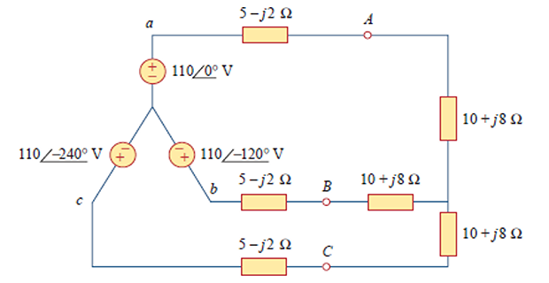
\[\begin{aligned}
\mathbf{V}_{p} &=110 \angle 0^{\circ} \mathrm{V} \\
\mathbf{I}_{p} &=6.81 \angle-21.8^{\circ} \mathrm{A} \\
\mathbf{S}_{s} &=-3 \mathbf{V}_{p} \mathbf{I}_{p}^{*}\\
&=-3\left(110 \angle 0^{\circ}\right)\left(6.81 \angle
21.8^{\circ}\right) \\
&=-2247 \angle 21.8^{\circ}\\
&=-(2087+j 834.6) \mathrm{VA} \\
\mathbf{S}_{L} &=3\left|\mathbf{I}_{p}\right|^{2}
\mathbf{Z}_{p} \\
\end{aligned}\]