Demonstrative Video
Introduction
-
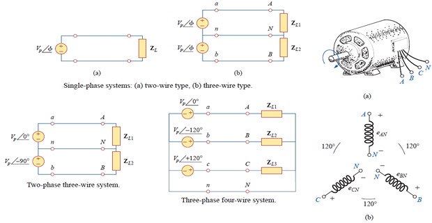
A single-phase ac power system consists of a generator connected through a pair of wires (a transmission line) to a load.
-
An ac generator designed to develop a single sinusoidal voltage for each rotation of the shaft (rotor) is referred to as a single-phase ac generator.
-
If the number of coils on the rotor is increased in a specified manner, the result is a polyphase ac generator, which develops more than one ac phase voltage per rotation of the rotor.
-
Three-phase system most frequently used for power transmission.
Polyphase System
-
In the normal household system is a \(1-\phi\) three-wire system because the terminal voltages have the same magnitude and the same phase
-
Circuits or systems in which the ac sources operate at the same frequency but different phases are known as polyphase
Advantages of\(3-\phi\)System over\(1-\phi\)System
For same Electric power:
-
Generation (Alternator) : Power to weight ratio \(\uparrow\), size \(\downarrow\), overall cost \(\downarrow\), Weight \(\downarrow ~\Rightarrow\) transportation and installation become convenient and less space is required.
-
T & D : conductor material \(\downarrow ~\Rightarrow\) economical
-
Under UPF condition:
-
Same condition of Power to weight ratio for 3-\(\phi\) IM (Load) and TF.
-
3-\(\phi\) Induction Motor are self-starting but 1-\(\phi\) not so some arrangements are required which increase cost.
-
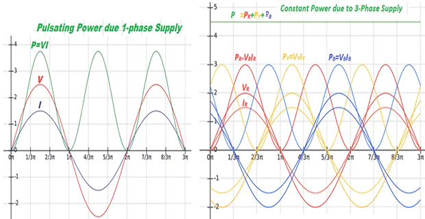
3-phase motor is having better power factor
-
Reliability under fault condition.
-
A \(3\phi\) system can feed a \(1\phi\) load, whereas vice-versa is not possible.
Balanced Three-Phase Voltages
-
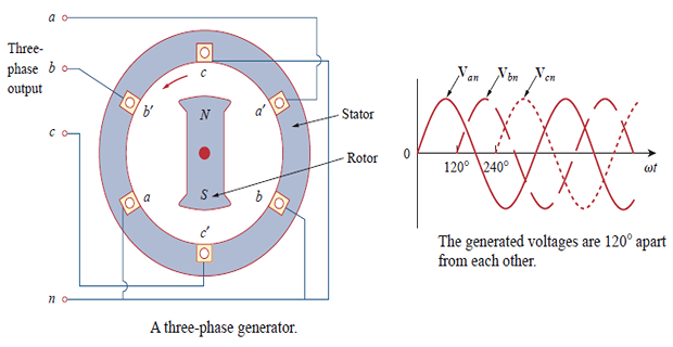
\(3-\phi\) voltages are produced by alternator having coils with terminals \(a-a^{\prime}\), \(b-b^{\prime}\), and \(c-c^{\prime}\) that are physically placed at \(120^{\circ}\) apart.
-
As the rotor rotates, its magnetic field cuts the flux from the three coils and then voltage is induced in the coils.
-
Induced voltages are equal in magnitude but out of phase by \(180^{\circ}\).
-
Balanced phase voltages are equal in magnitude and are out of phase with each other by \(120^{\circ}\)
-
A \(3\phi\) system \(\sim\) \(3 \times 1\phi\) circuits.
-
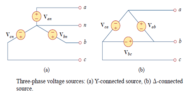
The voltage sources can be either Y-connected or delta-connected.
-
\(\mathbf{V_{an}}\), \(\mathbf{V_{bn}}\), \(\mathbf{V_{cn}}\) \(\Rightarrow\) Phase voltages
-
abc or positive sequence
-
produced when rotor rotates counter-clockwise
-
acb or negative sequence
-
produced when rotor rotates clockwise
-
The phase sequence is the time order in which the voltages pass through their respective maximum values.
-
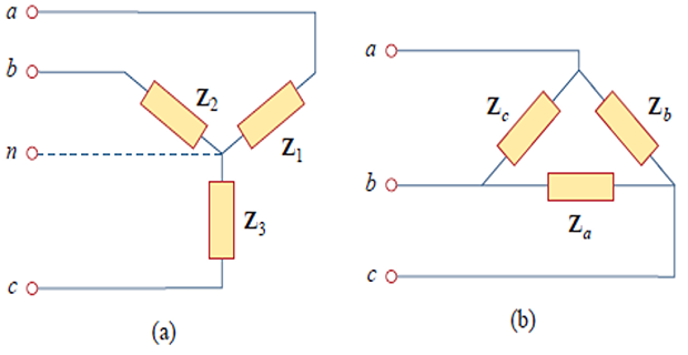
A balanced load is one in which the phase impedances are equal in magnitude and in phase.
-
For Balanced Loads:\[\begin{aligned} &\mathbf{Z}_{1}=\mathbf{Z}_{2}=\mathbf{Z}_{3}=\mathbf{Z}_{Y} \\ &\mathbf{Z}_{a}=\mathbf{Z}_{b}=\mathbf{Z}_{c}=\mathbf{Z}_{\Delta} \\ &\mathbf{Z}_{\Delta}=3 \mathbf{Z}_{Y} \quad \text { or } \quad \mathbf{Z}_{Y}=\frac{1}{3} \mathbf{Z}_{\Delta} \end{aligned}\]
-
Source-Load Combinations:
-
\(Y-Y\)
-
\(Y-\Delta\)
-
\(\Delta-Y\)
-
\(\Delta - \Delta\)
-
Problem
We notice that \(\mathbf{V}_{a n}\) leads \(\mathbf{V}_{c n}\) by \(120^{\circ}\) and \(\mathbf{V}_{c n}\) in turn leads \(\mathbf{V}_{b n}\) by \(120^{\circ}\). Hence, we have an \(acb\) sequence .