Demonstrative Video
Thevenin’s & Norton’s Equivalent Circuit
In a circuit, a particular element is variable (called load) while other elements are fixed
If variable element changes, entire circuit needs to be analysed all over again
Technique by which the fixed part of the circuit is replaced by an equivalent circuit
Used the concept of duality between voltage and current sources

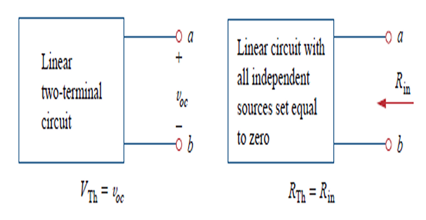
Thevenin’s Theorem
A linear two-terminal circuit can be replaced by an equivalent circuit consisting of a \(V_{th}\) in series with \(R_{th}\)
\(V_{th}\) : OC voltage at the terminals
\(R_{th}\) : input eq. resistance at the terminals when the independent sources are turned off
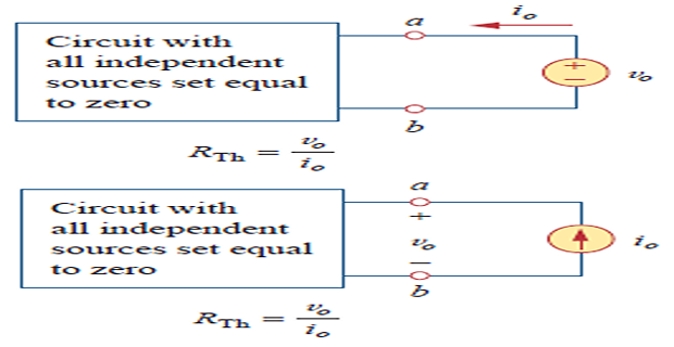
To find \(R_{th}\)
Case-1: No dependent source turn off all independent sources and determine \(R_{th}\) at input terminals
Case-2: If dependent sources are there turn off only independent sources and then determine \(R_{th}\) by applying 1 V or 1 A at input
The current through and voltage across the load can be easily determined
Norton’s Theorem
A linear two-terminal circuit can be replaced by an equivalent circuit consisting of a \(I_{N}\) in parallel with a \(R_{N}\)
\(I_{N}\) : short-circuit current through the terminals and
\(R_{N}\) : input equivalent resistance at the terminals when the independent sources are turned off.
\[\begin{aligned} R_N & = R_{TH} \\ I_{N} & = I_{sc} \\ \Rightarrow I_{N} & = \dfrac{V_{TH}}{R_{TH}} \end{aligned}\]
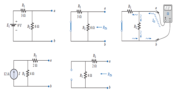
Measuring\(V_{oc}\)and\(I_{sc}\)
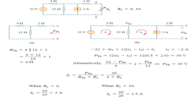
Solved Problem
